Hello everyone, welcome to<span>LiXin Embedded</span>.
In embedded development, whether it is sensors, memory chips, or GPIO expansion modules, the presence of I2C can be seen everywhere. In this article, we will start from the basic working principles of I2C and delve into common issues and their debugging methods.
Why Choose I2C
The I2C bus is popular for several reasons:
- Low Cost: Compared to SPI, which requires more pins, I2C can achieve communication with just two wires (SCL clock line and SDA data line), saving pins and effort. Compared to the differential signals of CAN bus, the physical layer design of I2C is also simpler.
- A single I2C bus can connect up to 127 slave devices, making it very friendly for scenarios that require multiple sensors or modules.
- The transmission rate of I2C typically ranges from 100Kbps to 400Kbps, which is sufficient for low-speed applications such as temperature and humidity sensors, fan control, and EEPROM read/write.
Of course, I2C is not a panacea. If higher bandwidth is required, such as for reading and writing NOR Flash chips, SPI would be a better choice; if extremely high reliability is pursued, the CAN bus commonly used in automotive electronics is more suitable; if only single-device communication is needed, serial communication is actually simpler and more direct.
The Essence of I2C Communication
The core of I2C communication is two signal lines: SCL (clock line) and SDA (data line). These two lines are pulled high by default through pull-up resistors, and devices communicate by pulling the signal lines low. Here are several key points of I2C communication:
1. The Mystery of Bit Transmission

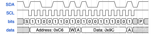
I2C is essentially digital communication, transmitting a series of 0s and 1s. The rules are simple: each time the SCL line generates a pulse, the level on the SDA line is sampled once, determining whether a 0 or 1 is transmitted. To ensure data stability, SDA must remain unchanged during the high level of SCL. For example, to transmit 0xC9 (binary 11001001), SDA will sequentially present the corresponding level changes, while SCL controls the rhythm.
2. Start and Stop Signals

The I2C bus supports multiple master devices, and to avoid confusion, clear start (START) and stop (STOP) signals are needed:
- Start Signal: When SCL is high, SDA is pulled low from high level, indicating the start of communication.
- Stop Signal: When SCL is high, SDA is released from low level to high level, indicating the end of communication.
These two signals act like the opening and closing remarks of communication, ensuring that the bus’s usage rights are clearly conveyed.
3. Addressing Mechanism

I2C is a multi-slave device bus; how do we specify the communication target? The answer is a 7-bit address. After each communication starts, the master device sends a 7-bit slave device address on the bus, along with a 1-bit read/write flag (0 for write, 1 for read). For example, sending address 0x66 followed by 0 indicates that the master device wants to write data to the slave device at address 0x66.
Address conflicts are a common issue, especially when multiple identical sensors are connected to the same bus. Fortunately, many chips support configuring part of the address bits through hardware pins or registers to flexibly handle conflicts. If it cannot be resolved, an I2C multiplexer can be used to isolate devices.
4. Read and Write Operations

The read and write operations of I2C are very intuitive. The master device tells the slave device whether to read or write data through the read/write flag. A typical scenario is to write first and then read: for example, to read the value of a certain register, the master device first sends a write command specifying the register address, and then sends a read command to obtain the register data. This operation is particularly common in EEPROM or sensor configuration.  It is worth mentioning that I2C does not have a formal mechanism for slave devices to actively initiate communication. If a slave device has data to report, it usually triggers an interrupt through an additional GPIO pin to notify the master device to read the data.
5. Acknowledgment Mechanism
The I2C protocol requires that after transmitting each byte, the receiver must send an acknowledgment bit (ACK/NACK). ACK is 0, indicating successful reception; NACK is 1, indicating reception failure or termination of transmission. For example:
- If NACK is received after sending the address, it may indicate that no device responded to this address.
- If NACK is received after writing data, it may indicate that the slave device does not recognize this command or that the buffer is full.
- When reading data, sending NACK usually tells the slave device not to send more data.
NACK is not necessarily an error; for example, when reading EEPROM, actively sending NACK can terminate the data stream.
6. Clock Stretching
The clock of I2C is controlled by the master device, but sometimes the slave device needs to slow down the pace. In this case, it can pull the SCL line low for clock stretching, allowing the master device to pause transmission and wait for the slave device to be ready. It is important to note that not all devices support clock stretching; if the master device does not support it and the slave device attempts to stretch, it may lead to communication errors.
I2C Debugging Practice
Although I2C is simple, various issues may arise during debugging, such as devices not responding, data being all 0, or the bus hanging. Here are some common problems and solutions:
Failed to Read Chip ID via I2C
Assuming you just received a new board and wrote a simple code to read the chip ID from the slave device, but it either reports an error or reads all 0s. Don’t worry, we will check from hardware to software step by step.
1. Check Device Compatibility
Although I2C is a standard protocol, some extended features may cause compatibility issues:
- Speed: The standard speed of I2C is 100Kbps, but many new devices support 400Kbps. If the master device uses 400Kbps while the slave device only supports 100Kbps, communication will definitely fail. The solution is to consult the slave device’s datasheet to confirm the supported speed and, if necessary, reduce the master device’s speed to 100Kbps.
- Clock Stretching: If the slave device supports clock stretching but the master device does not, it may cause communication to hang. In this case, it is recommended to first disable the master device’s clock stretching function to see if normal operation resumes.
2. Check Peripheral Configuration
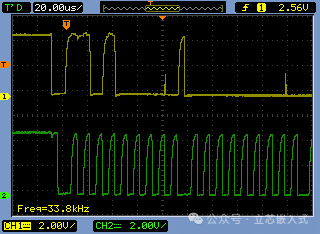
If compatibility is not an issue, the next step is to use a logic analyzer to capture the SCL and SDA signals and observe the waveforms:
- Signal Stagnation: If SCL and SDA remain high, it may indicate that the MCU’s I2C peripheral has not been initialized successfully. Check the following points:
- Has the I2C initialization function been called? Set breakpoints with a debugger to confirm.
- Are the I2C pin configurations correct? Some MCUs’ I2C peripherals can only be mapped to specific pins; incorrect mapping will lead to initialization failure.
- Is the clock source enabled? I2C peripherals usually rely on specific PLL or clock modules; consult the chip manual to ensure the clock configuration is correct.
- Signal Stuck: If SCL or SDA remains low, it may indicate an issue with the pull-up resistors.
3. Address Issues

If the logic analyzer shows that NACK is received after sending the address, it indicates that the slave device did not respond. Common reasons include:
- Incorrect Address: Logic analyzers typically display addresses in byte format, while the actual 7-bit address needs to be right-shifted by one bit. For example, displaying 0x30 may correspond to the 7-bit address 0x18. Consult the slave device manual to confirm the address is correct.
- Address Configuration: Some chips’ addresses can be configured via pins or registers. Check the schematic to ensure the configuration pin levels meet expectations.
- Address Conflict: List all device addresses on the bus and check for duplicates. If there are conflicts, adjust the hardware configuration or introduce an I2C multiplexer.
4. Slave Device Status
If the address is correct but there is still no response, the issue may lie with the slave device itself:
- Power Issues: Use a multimeter to check the power pins of the slave device to ensure the supply voltage is correct and stable. Some boards require manually enabling power management chips or MOSFETs.
- Reset Status: Check the reset pin of the slave device to ensure it is not pulled low.
- Enable Pin: Some chips have I2C enable pins; confirm their status is correct.
- Hardware Damage: If all the above are normal, try replacing the board or chip, as it may be damaged due to ESD (electrostatic discharge).
5. Pull-Up Resistors
The I2C bus relies on pull-up resistors to pull the signals high. If there is an issue with the pull-up resistors, communication will fail. Typically, pay attention to the following points:
- Use an oscilloscope to observe the SCL and SDA signals:
- Constant Low Level: This may indicate a missing pull-up resistor or that a device is pulling the bus low. Check the PCB layout to confirm that the pull-up resistors are soldered correctly. If there are resistors, remove the slave devices one by one until the signal returns to normal.
- Constant High Level: This indicates that no devices are communicating; return to the “Peripheral Configuration” section for checks.
- Smooth Waveform: If the signal edges are not sharp enough, it may indicate that the pull-up resistor value is too high, causing a long signal rise time. Try replacing it with a smaller resistor, such as 2KΩ; although the power consumption will be slightly higher, the signal quality will be better.
- Voltage Mismatch: Confirm that the bus voltage matches the device (commonly 3.3V or 1.8V); if not, a level shifter is needed.
Conclusion
Although the I2C bus protocol is not complex, debugging it can sometimes be frustrating. From hardware connections to software configurations, every step may have hidden pitfalls. I hope this article helps you avoid detours the next time you encounter I2C issues.