Introduction
Do you know how IoT devices and other hardware manufacturers debug and test their devices? That’s right, in most cases, they leave a serial interface, allowing them to read real-time debug logs or interact with the hardware through a shell. There are mainly two different types of serial interfaces, but the most common one is the Universal Asynchronous Receiver-Transmitter (UART).
In this article, we will discuss how to connect to the TP-Link WR841N (v9.0) via UART, with the entire hands-on operation taking about five minutes.
UART
Before we begin, I would like to briefly introduce the working mechanism of UART. If you are already familiar with it, you can skip this section.
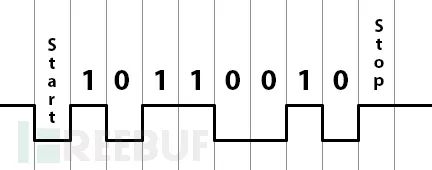
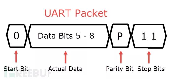
UART stands for Universal Asynchronous Receiver-Transmitter. Unlike other serial interfaces, it is a serial communication interface that does not rely on a clock. It can be used in scenarios such as unidirectional communication, half-duplex communication, or full-duplex communication, with communication primarily achieved through data packets:
Finding the UART Interface
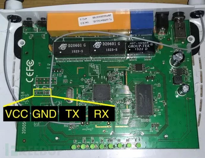
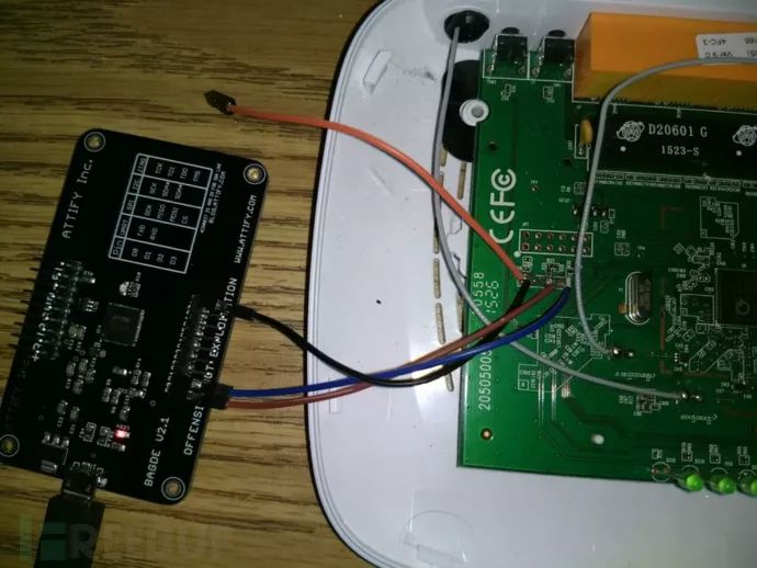
The UART interface is located on the physical device’s circuit board, typically as a panel with 3 or 4 pins. In our analysis scenario (TP-Link WR841N v9.0), the port situation is shown in the image below:
Once you find the UART port, we also need to distinguish the function of each pin (GND, VCC, TX, RX). At this point, we need to follow these steps:
1. Identify GND: Turn off the device, set your multimeter to ‘continuity mode’, connect the black probe to ground (or another metal), and then touch the red probe to each of the four pins. If you hear a beep, that pin is GND.
2. Identify VCC: Set the multimeter to ‘DC Voltage (V-)’, connect the black probe to GND, and then check the UART pins with the red probe. If any pin shows a constant high voltage (about 3.3V or 5V), that pin is VCC.
3. Identify TX: During the first 10-15 seconds of the boot process, the TX pin will cause significant voltage fluctuations due to the large amount of data being transmitted. The method is the same as for finding the VCC pin.
4. Identify RX: The RX pin will have the lowest voltage throughout the process, which doesn’t require much explanation.
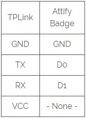
After identifying all the pins, you can solder some connectors onto them (Attify Badge):
Interacting with the Device via UART
Before we actually communicate with the UART interface, we need to determine the baud rate. The baud rate refers to the frequency of data transmission between devices, in other words, how many bits of data are transmitted per second. Common baud rates are 9600, 38400, 19200, 57600, and 115200, but manufacturers can theoretically set it arbitrarily.
We can use the devttys0 Python script to quickly find the appropriate baud rate:
$ git clone https://github.com/devttys0/baudrate
$ cd baudrate
After downloading, we will power on the TP-Link router and run the Python script while turning on the device:
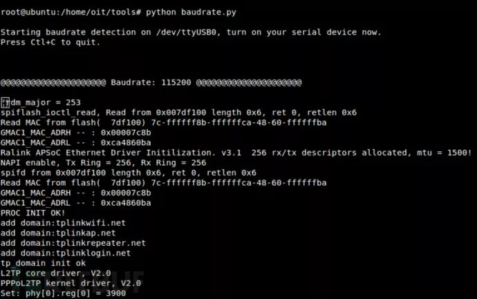
$ sudo python baudrate.pyThen, you can use the up and down keys to scan different baud rates, which is similar to adjusting the frequency on a radio.
In our test scenario, the baud rate used by the TP-Link router is 115200.
To interact with the device via UART, we need to run the following command:
screen /dev/ttyUSB0 115200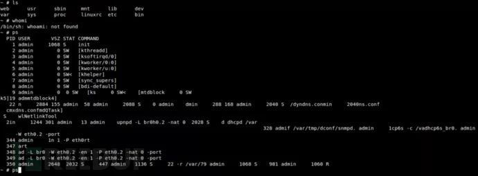
Boom!! We successfully gained root access to the shell! Yes, it’s that simple! You can now freely view or modify the device’s file system.
Unexpected Situations
Here are some interesting situations I encountered during testing.
TP-Link’s Security is Quite Concerning
Recently, I also tested the TP-Link WR841N v.9 and v.20, and I found that when I tried to access the shell of the v.9 router via UART, it required me to enter a username and password. However, the v.20 router directly granted me access to the device shell.
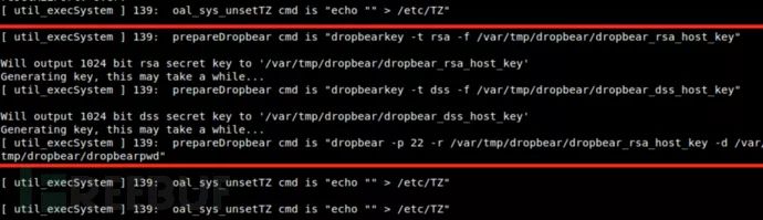
UART + First Boot = Boot Failure
If the device fails to boot on the first attempt after connecting UART, you can disconnect the TX and RX connectors, then reconnect them when rebooting the device. You will then see the Dropbear rsa/dss key creation information:
Future Research
My main goal now is to create backdoors in these routers via UART, create malicious firmware, or modify specific files on the target device. Additionally, I will analyze the differences between these two versions of the router. I hope this article can provide some insights for your hacking endeavors.
* Source: konukoii, FB editor Alpha_h4ck compiled, please indicate the source as FreeBuf.COM