1. Self-Diagnosis of LIN BusWhen performing self-diagnosis on the LIN data bus system, the address code of the LIN master control module must be used. The self-diagnostic data is transmitted from the LIN slave control module to the LIN master control module via the LIN bus. All self-diagnostic functions can be completed on the LIN slave control module.
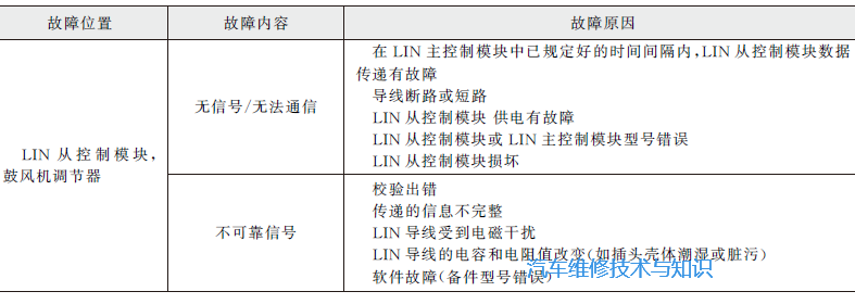
For example, the fault information of the blower regulator is shown in the table below.
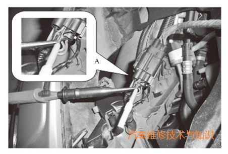
2. Oscilloscope Measurement Method for LIN SignalsBelow, we take the xenon headlight module of the Volvo series as an example to illustrate the measurement method of LIN signal waveforms.(1) Input Port ConnectionRefer to the circuit diagram and related information to determine the pin of the LIN bus, then connect the red voltage probe of the oscilloscope. The other end of the red voltage probe is connected to input channel A of the oscilloscope, as shown in the figure below.
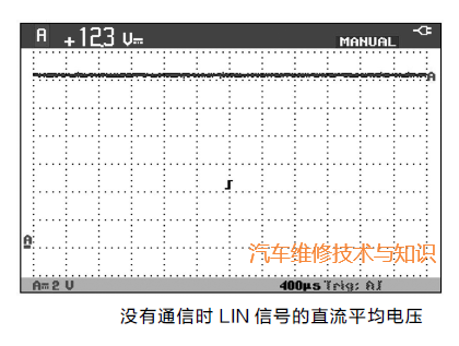
(2) DC Average Voltage Testing MethodSet the oscilloscope accordingly to test the DC average voltage of the LIN signal. When there is no data communication, the DC average voltage of the LIN signal is approximately 12V, which is also the resting voltage of the LIN signal, as shown in the figure below.
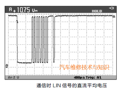
When there is data communication on the LIN bus, the DC average voltage of the LIN signal is about 10V, and it varies dynamically, as shown in the figure below.
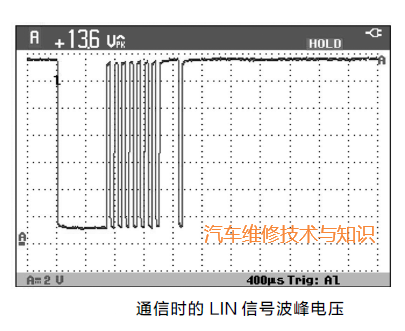
(3) Peak Voltage Testing MethodSet the oscilloscope accordingly to measure the peak voltage of the LIN signal during communication, which is approximately the battery voltage, as shown in the figure below.
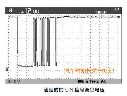
The trough voltage of the LIN signal during communication is approximately 1V, as shown in the figure below.
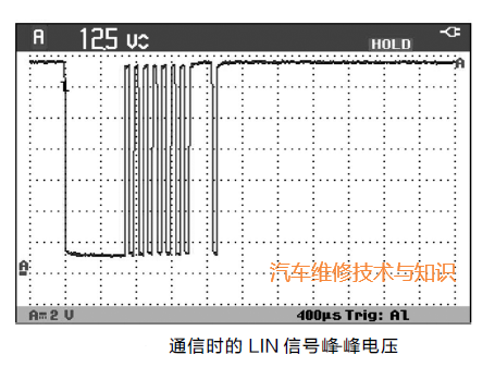
The peak-to-peak voltage of the LIN signal during communication is approximately 12V, as shown in the figure below.
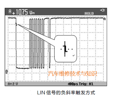
(4) Triggering Method SettingsTo successfully capture the complete LIN signal waveform, it is recommended to set the oscilloscope’s triggering method to negative slope triggering, as shown in the figure below.
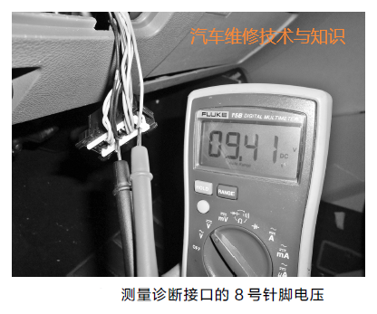
3. Multimeter Measurement Method for LIN SignalsWhen measuring the LIN bus, it is important to note that when the LIN bus is not transmitting data, the voltage is 12V; LIN is a master-slave protocol bus, and all actions of the slave control unit must be controlled by the master module. For example, if the wire between the air conditioning control panel and the display is disconnected, the display will not change and will remain in the state it was in when disconnected; only after power is cut will the information be lost. When the LIN is interrupted, it will affect the master control unit. For instance, if the air conditioning panel and display are interrupted, it may cause the air conditioning to turn on automatically.In some vehicle models, the diagnostic interface connects to the LIN bus, with pin 8 being the relevant pin. Therefore, the LIN signal voltage at pin 8 can be measured using the diagnostic interface, as shown in the figure below.
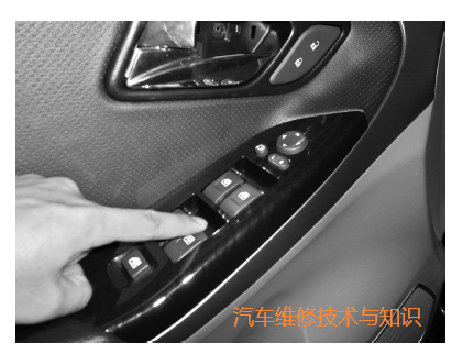
During the measurement process, relevant components can be operated, such as the driver-side door control panel, to send commands from the master control unit via the LIN bus, as shown in the figure below.
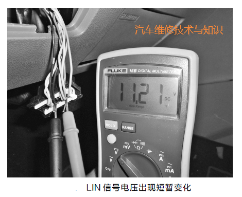
If the command can be sent normally, the LIN signal voltage will show a brief change, indicating that the command transmission is normal; otherwise, relevant parts and wiring harnesses should be checked, as shown in the figure below.
Related Articles more
- [Case Analysis] Automotive LIN Bus Technology Case Analysis
- Key Components and Technical Fault Solutions of CAN Bus Systems
- 9 Steps to Teach You How to Repair CAN Main Bus Short Circuit Faults
- [Case Analysis] Automotive Bus Fault Repair Cases
- Common Faults and Diagnostic Methods of FlexRay Bus Systems
- Types of Automotive Buses, Fault Characteristics & Case Analysis
- Steps, Methods, and Precautions for Diagnosing CAN Bus System Faults
- What Are the Uses of Automotive Multimeters in Fault Repair, and How to Use Them?
 Click below “Read the Original” to recharge with us!
 I appreciate your likes and shares!