Name: Design of a Sine Wave Signal Generator Based on FPGA: VHDL Code and ISE Simulation
Software: ISE
Language: VHDL
Code Function: Using ISE to design a 14-bit sine wave signal generator based on the Xilinx DDS IP core; control the number and frequency of the output sine wave signals by manipulating the enable signal and the internal frequency control register of the DDS IP core, and perform simulation verification.
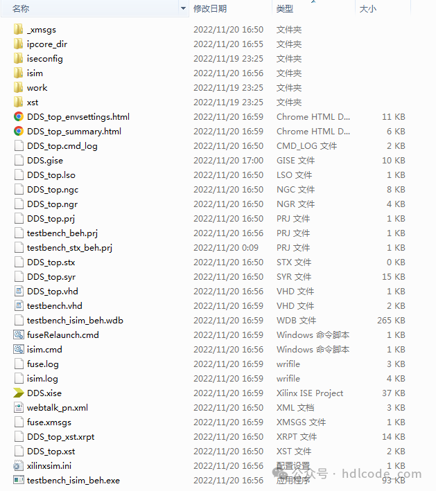
1. Project Files
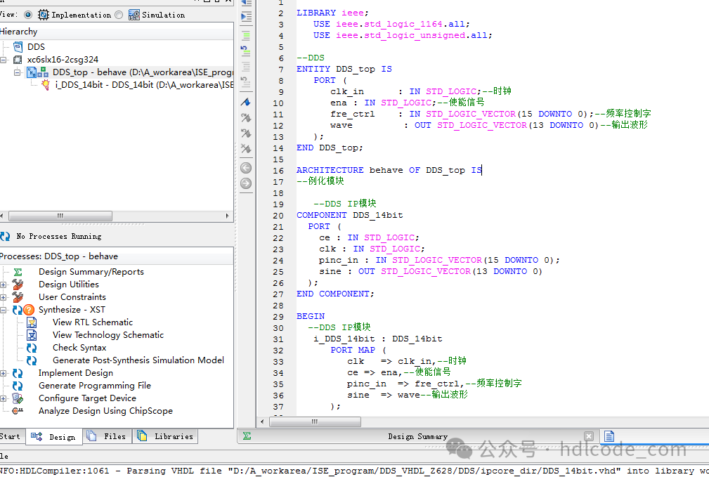
2. Program Files
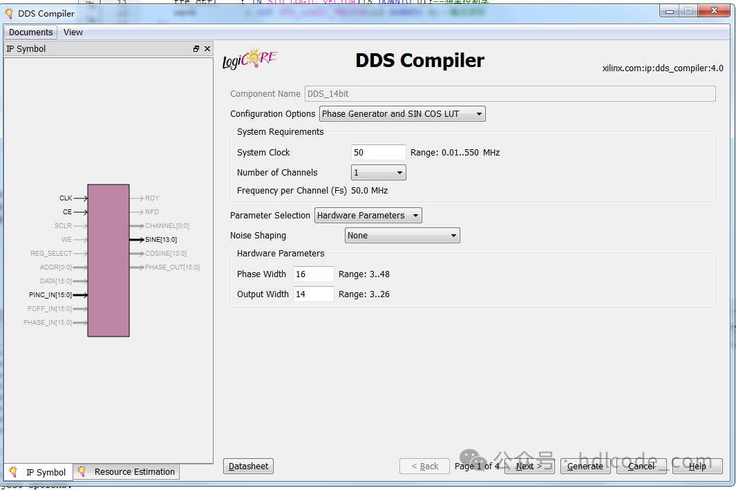
DDS IP Core
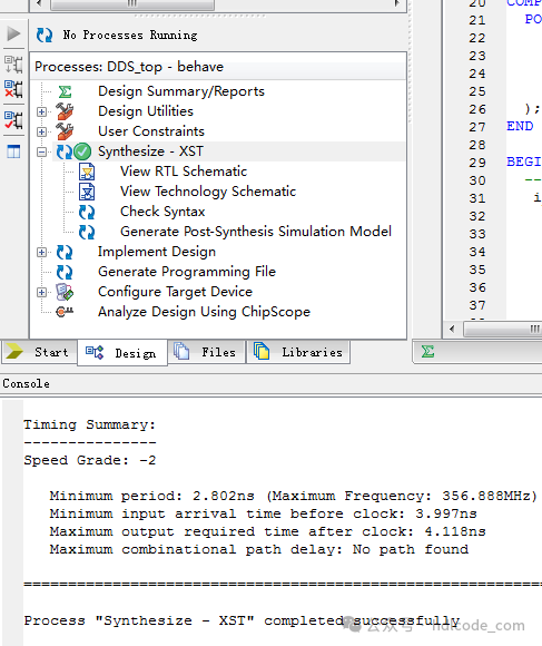
3. Program Compilation
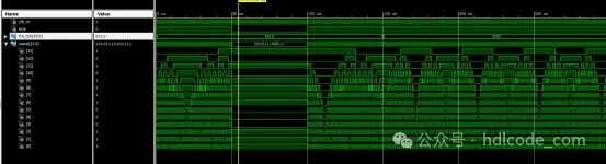
4. Testbench
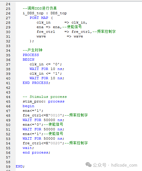
5. Simulation Diagram
Partial Code Display:
LIBRARY ieee;
   USE ieee.std_logic_1164.all;
USE ieee.std_logic_unsigned.all;
--DDS
ENTITY DDS_top IS
   PORT (
      clk_in      : IN STD_LOGIC;--Clock
ena : IN STD_LOGIC;--Enable signal
fre_ctrl    : IN STD_LOGIC_VECTOR(15 DOWNTO 0);--Frequency control word
   wave         : OUT STD_LOGIC_VECTOR(13 DOWNTO 0)--Output waveform
   );
END DDS_top;
ARCHITECTURE behave OF DDS_top IS
--Instantiate module
   --DDS IP module
COMPONENT DDS_14bit
  PORT (
    ce : IN STD_LOGIC;
    clk : IN STD_LOGIC;
    pinc_in : IN STD_LOGIC_VECTOR(15 DOWNTO 0);
    sine : OUT STD_LOGIC_VECTOR(13 DOWNTO 0)
  );
END COMPONENT;

BEGIN
  --DDS IP module
   i_DDS_14bit : DDS_14bit
      PORT MAP (
         clk   => clk_in,--Clock
ce => ena,--Enable signal
         pinc_in  => fre_ctrl,--Frequency control word
         sine  => wave--Output waveform
      );

END behave;