 Search on WeChat
 Automation Knowledge Base
Hello everyone! Today I want to talk about a knowledge point that I learned through practical experience—how PLCs control stepper motors.
I remember the first time I encountered a stepper motor, I spent a long time looking at the manual, my mind filled with terms like “pulse count” and “frequency”. It wasn’t until I successfully connected and debugged it that I realized the principles weren’t that complicated. Today, I will explain these concepts in straightforward terms so that even beginners can understand them!
🔍 First, let’s understand: What can stepper motors do?
Let’s start with the basics. Stepper motors excel at “precise positioning”. For example, I previously created a positioning device for a small conveyor belt, using it to control the belt to stop at a specified position.
The control logic is quite intuitive: The number of pulses sent by the PLC determines the angle it turns (the angle turned corresponds to the distance the device moves); The speed at which the PLC sends pulses determines how fast the motor turns.
However, one thing to remember is that stepper motors are more suitable for applications where precision is not extremely high, such as positioning in small assembly lines or simple robotic arm movements. They are simple, inexpensive, and easy to debug. For applications requiring millimeter-level or higher precision, such as precision machine tools, a servo system is needed, which we will discuss in detail next time.
🤝 Core Combination: Is the Stepper System a “Triangle of Iron”?
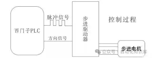
Many beginners think that they can connect a stepper motor directly to a PLC, but that’s not the case. A complete stepper system consists of a “stepper driver + stepper motor” combination, just like driving a car—the motor is the wheels, and the driver is the engine; you can’t have one without the other.
For example, using the Siemens PLC I commonly used, the stepper driver acts as a “translator” and “amplifier”: it first receives the pulse and direction signals from the PLC, processes and amplifies these signals, and then sends them to the stepper motor, which then knows which direction to turn, how much to turn, and how fast.
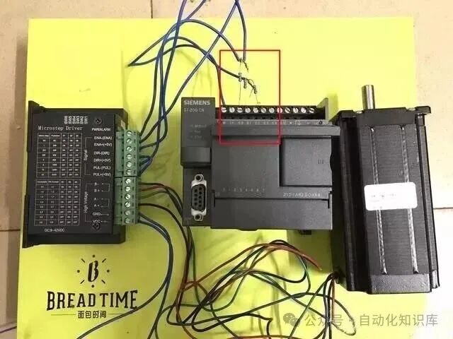
Here’s a practical diagram I took when setting up this basic system:
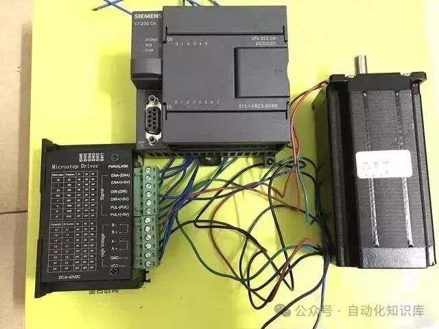
Stepper Driver + Stepper Motor + Siemens PLC (CPU 222 CN)
📚 3 Key Concepts to Understand for Beginners
These concepts are the core of debugging. I initially grasped these points, which made subsequent wiring and debugging smooth. Let’s go through them one by one, based on my actual experiences.
1️⃣ Driver: The “Power Manager” of the Motor
I mentioned the role of the driver earlier, but let’s elaborate. The signals output by our PLC are actually quite “weak” and cannot drive the stepper motor directly. The driver is responsible for amplifying this weak signal into a power signal that the motor can handle, while also controlling the motor’s operating state based on parameters we set, such as microstepping and current.
In simple terms, the PLC is the “commander issuing orders”, the driver is the “aide conveying commands and empowering the soldiers”, and the motor is the “soldier executing the tasks”.
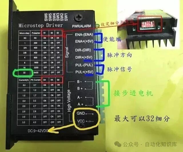
Here’s a detailed image of the driver, showing the interfaces and parameter knobs:
2️⃣ Step Angle: The “Minimum Step Size” of the Motor
The step angle is the minimum angle the stepper motor can turn with one pulse from the PLC. The most common stepper motor on the market has a step angle of 1.8°, which is set at the factory and generally cannot be changed.
For example, when I used a 1.8° motor to create a rotating platform, it needed to turn one full circle (360°) to rotate the platform one full circle. How many pulses does the PLC need to send?
Calculating gives us: 360° ÷ 1.8° = 200 pulses. This means that if I set the PLC program to output 200 pulses, the motor will turn exactly one full circle, and the platform will also turn one full circle. Isn’t that straightforward?
3️⃣ Microstepping: A Small Trick to Make the Motor “Turn More Smoothly”
This feature was a “lifesaver” during my debugging. When I first used a 1.8° motor, I noticed that the motor was a bit “jittery” during rotation, causing the conveyor belt to shake and the positioning error to be larger than expected. After consulting an experienced technician, I learned that I hadn’t enabled the “microstepping” feature.
Microstepping essentially divides a step angle into several smaller steps by adjusting the DIP switches (some are toggle switches, others are knobs) on the driver. For example, with a 1.8° step angle, if I set it to 10 microsteps, then when the PLC sends one pulse, the motor will only turn 0.18°, resulting in much smoother rotation and smaller errors.
Using the previous example of a full rotation, how many pulses are needed with 10 microsteps? 360° ÷ 0.18° = 2000 pulses. Although the number of pulses has increased, the motor turns smoothly and accurately, which is worth it!
To summarize: the larger the step angle, the fewer pulses are needed for a full rotation, but the more jittery the motion; the smaller the step angle (the more microsteps), the more pulses are needed for a full rotation, but the motion is smoother and more precise.
🔧 Practical Tips: Detailed Hardware Explanation of the Stepper System (Includes Wiring Diagram)
Now that we’ve covered the theory, let’s get practical. I will use the commonly used Pufide stepper motor as an example to explain how to view and connect the hardware.
1️⃣ Stepper Driver: Two Control Methods to Choose From
The most critical aspect of the driver is the control method, which mainly has two types that I have used, and I will explain the differences:
A) Pulse + Direction Control (Most Common)
This method is straightforward: connect the PUL interface to the PLC’s pulse output terminal and the DIR interface to the PLC’s direction control terminal. When the PUL interface receives a pulse, the motor turns; whether the DIR interface signal is high or low determines whether the motor turns forward or backward. I used this method for positioning the conveyor belt, as it is the fastest to debug.
B) Forward Pulse + Reverse Pulse Control
This method means that when the PUL interface receives a pulse, the motor turns forward, and when the DIR interface receives a pulse, the motor turns backward. However, one must note that PUL and DIR cannot send pulses simultaneously; otherwise, the motor will be “confused” and won’t know which direction to turn. I generally use this method in scenarios requiring frequent forward and backward movements, such as small feeding machines.
Here’s a diagram of the Pufide driver for reference:
2️⃣ Stepper Motor: Pay Attention to the Winding Connections
Stepper motors are generally two-phase, with A and B windings. When wiring, ensure to connect to the A+, A-, B+, and B- terminals on the driver; do not connect them incorrectly. If connected incorrectly, it’s not a problem; the motor will just rotate in the opposite direction, and you can adjust the wiring.
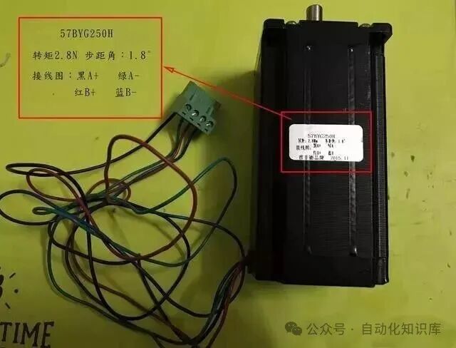
Here’s a parameter diagram of the motor, which clearly indicates the resistance, current, and other key parameters of the windings. It’s best to verify these before wiring:
3️⃣ Wiring to the PLC: Don’t Forget This Resistor!
Here’s an important point! When wiring, there’s a pitfall I fell into that you should avoid. The Siemens CPU 222 CN PLC I used has an output voltage of 24V, while the signal voltage of the stepper driver is 5V. If you connect the PLC’s output directly to the driver, it could burn out the driver!
The method taught to me by an experienced technician is to place a 1.2KΩ, 1/4W resistor in series between the PLC output and the driver signal terminal to reduce voltage and limit current. I found a color-coded resistor and soldered it in, and after connecting it, I successfully debugged it on the first try.
Here’s a wiring diagram I drew, with the red part indicating the critical resistor:
💡 Finally, a Key Knowledge Point
The Siemens PLC (like the CPU 222 I used) can output two types of high-speed pulses to control the stepper driver:
1. PTO Pulse: The duty cycle is fixed at 50%, meaning the high and low levels are equal in duration, suitable for controlling stable speed scenarios, such as a conveyor belt running at a constant speed.
2. PWM Pulse: The duty cycle can be adjusted, meaning the ratio of high to low time can be changed, suitable for scenarios requiring speed adjustment, such as a feeding machine that accelerates from slow to fast.
We just need to call the corresponding high-speed pulse instructions in the PLC program, set the pulse count and frequency, and we can easily control how much and how fast the stepper motor turns.
🎯 To Summarize
In fact, the logic of PLC controlling stepper drivers is not complicated. The core is “pulse controls angle, frequency controls speed”, and remember these key points: “the driver is the bridge, the step angle is the foundation, and microstepping stabilizes precision”. Pay attention to voltage matching during wiring, and you can handle most scenarios.
I went from being completely confused to successfully debugging it independently in just half a day, mainly by grasping these basic concepts and then connecting the wires and adjusting the parameters. If you have any questions or encounter issues during practical operations, feel free to discuss in the comments, and we can exchange ideas together!
If you find this useful, don’t forget to click “See” and share it with friends who need it!
Previous Recommendations
Electrical Experts Share: 12 PLC Programming Tips to Help Beginners Avoid 3 Years of Pitfalls
PLC Engineers’ Secret Tips: View Code Flow Directly on HMI, No Need to Panic When Equipment Stops!
Electrical Technicians’ Secret Wiring Diagrams for Meters! No More Fear of “Looks Easy, But Fails When Connected”
Electrical People’s Secret Cable Code Guide! 90% of Peers Have Saved It
Electrical Technicians’ Go-To Analog Conversion Techniques, Easy for Beginners to Master!
Must-Read for Beginners! S7-200SMART Circle Drawing Practical Guide, Includes Complete Program for Free!
Siemens S7-1200 PLC Programming: Practical Guide with Parameter FC Block, Understandable for Beginners!
How to Write Practical PLC Alarm Programs? Save This Practical Experience, Beginners Can Also Get Started!
No Need to Go to the Workshop! 1:1 Virtual Simulation Platform, Practice PLC Debugging at Home
PLC Advanced Practice: I Used SCL Language for Material Sorting, Steps Are Super Detailed!
Share this
Save this Click to Save
 Click to See
 Click to LikeClick to FollowSo You Can Find Me Next Time