
I exerted a tremendous effort to finally blow off the STM32H753 with over 200 pins from the PCB using a hot air gun. I breathed a sigh of relief, silently hoping for a miracle. We need to design a new project, and after extensive analysis and consideration, we finally chose the STM32H753 chip. Due to the high demand for IO ports, we opted for a 208-pin package. Once we completed the PCB design, we wasted no time in arranging for PCB prototyping, material preparation, and assembly. After more than half a month, the PCBA was returned to us with the components soldered. We eagerly began debugging, hoping our creation would run smoothly. However, when I tested all the power supplies on the board with a multimeter in short circuit mode, I found that the MCU’s power supply was short-circuited, while the other power supplies were normal. My first reaction was to observe the soldering condition of the MCU pins with a magnifying glass, and I found that some pins seemed to be soldered together. I thought the chip must not have been placed correctly, causing a solder bridge; just dragging the IC should fix it. To my surprise, after dragging the IC, I measured the MCU’s power supply again, and it was still short-circuited. I cleaned the PCB with washing water and examined each MCU pin’s soldering condition with a magnifying glass, but found no issues with solder bridges. Yet, it still measured as a short circuit. There was a 0-ohm resistor in series between the MCU’s power supply and the front-end LDO output. After removing this resistor and measuring the LDO’s output, I found no signs of a short circuit, but the MCU’s power supply was still short-circuited. I was left with two paths: one was to desolder the MCU for measurement to see if the chip itself was short-circuited; the other was to sequentially remove and measure the surrounding filtering and decoupling capacitors to identify which capacitor was short-circuited. Based on my previous methods, I would have immediately desoldered the MCU to find out if the chip was short-circuited, as that would be the fastest way to troubleshoot. However, this MCU has over 200 pins, and whether I could remove it without damaging it was a concern, as was the ability to solder it back. Considering all this, I was apprehensive and temporarily gave up on desoldering the chip, opting instead to sequentially remove the filtering and decoupling capacitors. After removing each capacitor, I used a multimeter to check for short circuits. After removing over a dozen capacitors, the short circuit still persisted. With no other options, I had to bite the bullet and desolder the MCU. I first used a small nozzle on the hot air gun, circling clockwise for several minutes, but the MCU showed no response. Switching to a larger nozzle, I tried again for a few minutes, but it still didn’t budge. I continued, alternating between clockwise and counterclockwise for over ten minutes, but to no avail. Finally, I discarded the nozzle and directly aimed the hot air gun at the MCU. Indeed, great force yields miraculous results; after a few minutes, the MCU became loose, and I gently pried it up with tweezers. After removing the MCU, I sighed in relief, hoping there would be no more short circuits. However, things were not as simple as I thought. When I measured with the multimeter, it beeped incessantly… This was frustrating; everything that could be removed had been, so could it be a PCB short circuit? That shouldn’t be the case; modern PCBs are tested with flying probes, and any short circuit would have been detected before delivery. I examined the power supply traces of the MCU with a magnifying glass, but saw no signs of a short circuit. I also opened the PCB file to check the electrical characteristics and found no spacing errors. I checked the Gerber files sent to the board factory and found no shorts there either. Just when I was about to give up, I browsed through the schematic and accidentally discovered a clue. The MCU has a low voltage detection pin, which should either be connected to ground with a 0-ohm resistor or connected to VCC with a 0-ohm resistor. However, the schematic showed both resistors as 0R with no NC. I quickly checked the PCB and found that both corresponding resistors were soldered in. No wonder there was a short circuit; the power supply had already been connected to ground through these two 0-ohm resistors.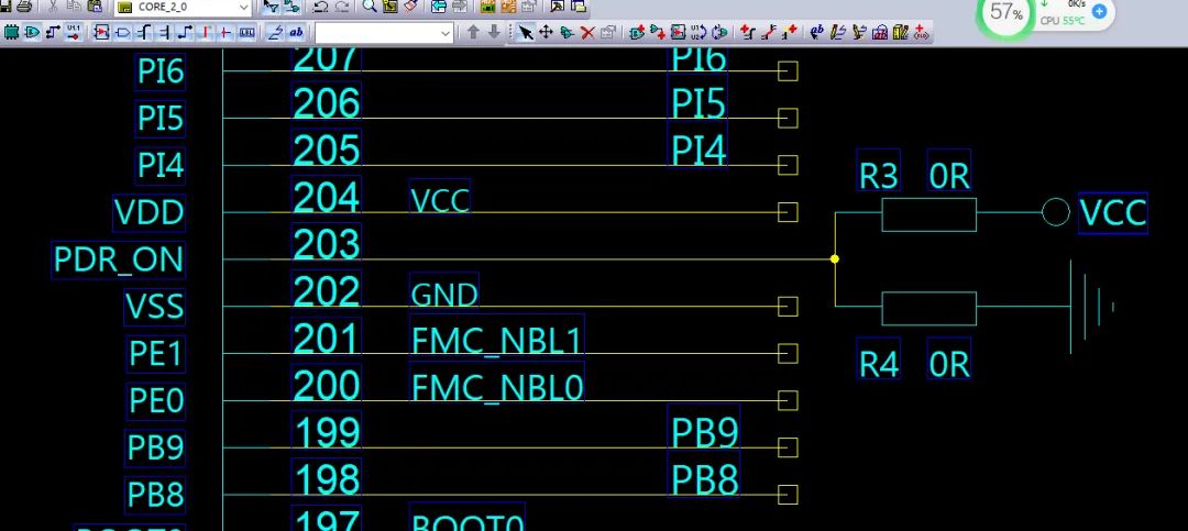 I desoldered one of the ground 0-ohm resistors, and after measuring with the multimeter, it was silent; it turned out those two resistors were the cause of the short circuit. Suddenly, a sense of accomplishment washed over me, and a smile appeared on my face. Next, another challenge awaited: to solder back the IC with over 200 pins. I carefully aligned the package, secured the IC, and began soldering. My skills at soldering ICs had diminished, and I frequently encountered issues with pin connections. After adding solder and flux and fiddling for half a day, I finally managed to solder the IC back and also reattached the capacitors. I thought this would conclude the matter, but unexpectedly, when I measured the MCU’s power supply network with the multimeter, it was short-circuited again, and I was back to square one. Frustrated, I felt like screaming. Taking a deep breath, I calmed down and thought, could it be that the IC was not soldered properly? I resoldered it and checked each pin’s soldering condition with a magnifying glass, confirming there were no shorts. However, the multimeter still indicated a short circuit. Could it be that the chip was soldered in the wrong orientation? This chip was a bit tricky, as there was a dot on each corner; I had soldered it based on the usual method where the silkscreen is horizontally placed, with the top left corner as pin one.
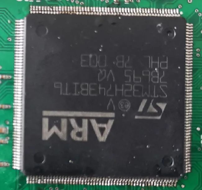 So, I checked the chip’s datasheet and found that the pin corresponding to the dot actually has a smaller dot inside it. Upon comparison, I realized it was indeed soldered incorrectly. The thought of having to desolder the chip again made me want to cry. With no choice, I had to desolder it. After a long day of struggle, I finally removed the chip, carefully checked the orientation several times, and resoldered it. Finally, after measuring with the multimeter, there was no short circuit, but I couldn’t feel happy anymore. After a whole day of effort, it turned out to be just a resistor issue that could have been resolved in a minute, yet I had wasted an entire day.
 Free Application

👆 Scan the QR code above to apply for the nPM1300 power management IC for free 👆
The nPM1300 evaluation kit (EK) allows for simple evaluation and no-code configuration of the nPM1300 power management IC (PMIC). By connecting to the nPM PowerUP application in nRF Connect for Desktop, all settings of the nPM1300 can be easily configured through an intuitive GUI and exported as code for implementation in MCU applications.
This kit features a JST battery connector for batteries with or without an internal NTC, as well as a male header for connecting all nPM1300 connections. Additionally, the kit includes three LEDs and four buttons, enabling simple evaluation of the PMIC’s GPIO and LED drivers.