Table of Contents:
1. Introduction and Origin of PLC
1.1 Introduction to PLC
1.2 Origin of PLC
2. Basic Structure of PLC
2.1 Composition of Basic Units
2.2 Expansion Modules
3. External Wiring of PLC
3.1 PNP and NPN Wiring
3.2 NPN and PNP Settings of PLC
4. Programming Languages
4.1 Graphical Programming
4.2 Textual Programming
1. Introduction and Origin of PLC
1.1 Introduction to PLC
PLC stands for Programmable Logic Controller, which is essentially an industrial control computer developed for specific applications. It not only has the core of a computer but is also equipped with many devices that make it suitable for industrial control. However, it is a general-purpose machine that cannot be used on any specific industrial equipment without secondary development.
However, secondary development of PLCs is quite easy, and they have many advantages such as small size, high reliability, strong anti-interference capability, complete control functions, strong adaptability, and simple installation and wiring.
General electrical engineers need to master: PLC programming, touch screen programming (Mitsubishi PLC – Xinjie Human-Machine Communication (Programming)), position control (Mitsubishi PLC Position Control Theory 1), analog signals (temperature, pressure, PID control, etc.).
Senior electrical engineers also need to master: network communication, visual recognition, and even upper computer C#, WinCC, Labview, etc.
1.2 Origin of PLC
The original purpose was to replace mechanical switch devices (relay modules). Imagine using a large number of electrical components (intermediate relays, time relays, etc.) in a large and complex device; the wiring would be extremely complicated, and maintenance would be a significant issue in the future.
Since 1968, the functions of PLCs have gradually replaced relay control panels. Modern PLCs have more functions, extending their use from single process control to control and monitoring of entire manufacturing systems.
2. Basic Structure of PLC
2.1 Composition of Basic Units
PLC mainly consists of MCU, input/output interfaces, power supply, and programming devices, as shown in Figure 2.1.1 below.
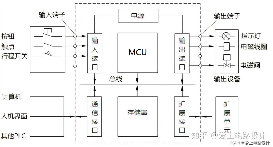
Figure 2.1.1 Composition of PLC
1) MCU Module
MCU Module consists of a microprocessor and memory, which reads various switch input signals (referred to as input signals); reads program instructions, compiles and executes instructions; and finally sends the computation results to the output terminal to control external loads.
MCU is the core of the entire PLC, equivalent to the human brain. For the differences and similarities between PLC and microcontrollers, please refer to: Differences and Similarities between PLC and Microcontrollers, and for practical project references: Detailed Explanation of PLC Programming Ideas with Examples.
2) Input and Output Modules
(1) The input module accepts and collects input signals, inputting the signals generated by buttons, limit switches, etc., to the MCU; it also inputs analog signals provided by potentiometers and various transmitters to the MCU.
(2) The output module is used to control external loads, including contactors, solenoid valves, and other actuators, as well as display and alarm devices.
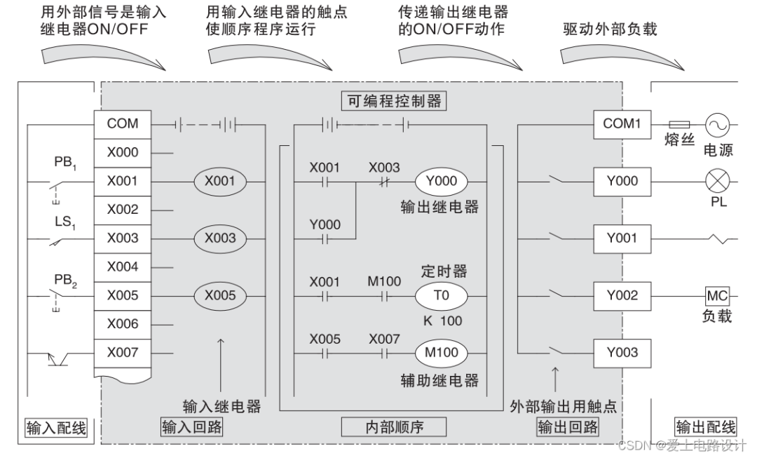
Figure 2.1.2 Input and Output Modules (Excerpt from Mitsubishi Specifications)
3) Power Supply Module
The power supply of the PLC generally uses a 220V AC power supply, which is converted into the DC power required by each unit in the system through a switching power supply module. Some power supply units also provide a 24V isolated DC power supply for use with passive switches connected to the input module.
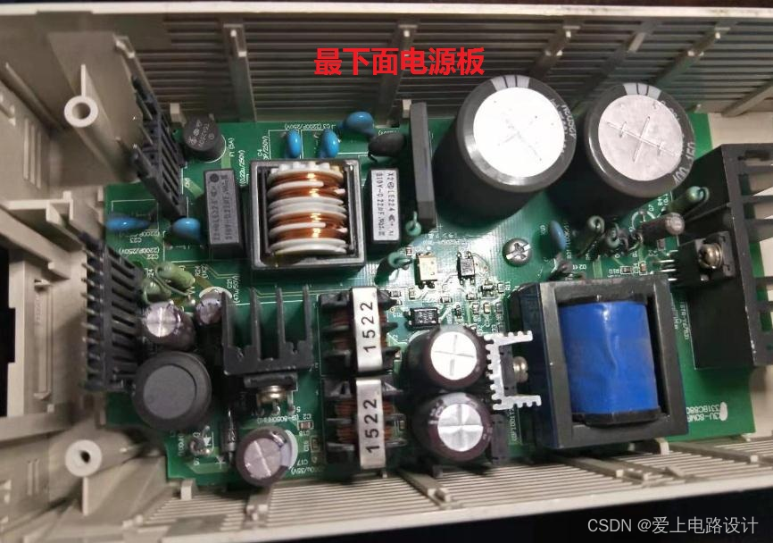
Figure 2.1.3 Image from: PLC Maintenance – Hechuan HCA8-32X32YT
4) Programming Devices
Generally a combination of a computer and programming cable, where the computer connects to the programming cable, which in turn connects to the PLC.
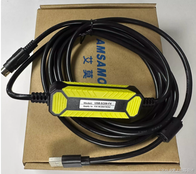
Figure 2.1.4 PLC Programming Cable
2.2 Expansion Modules
In addition to the basic units, PLCs also have expansion modules (such as input/output modules, communication modules, analog modules, etc.), and special function modules that connect to it to achieve more functions.
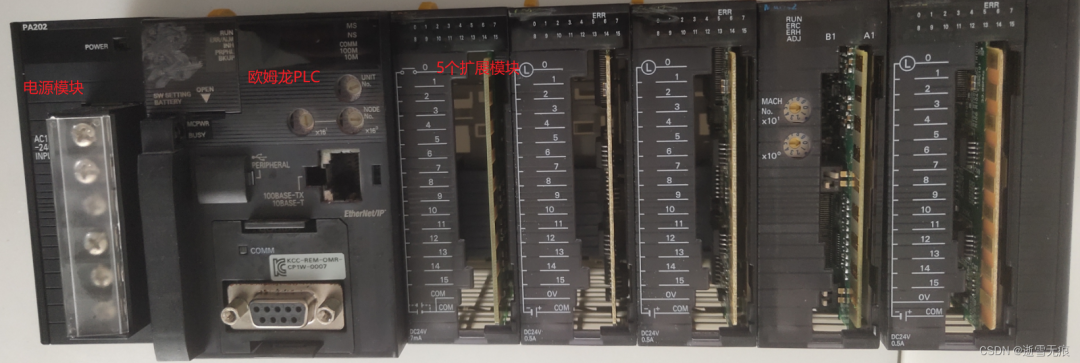
Figure 2.2.1 Image from: Salt Spray Test Equipment Maintenance – Omron PLC
3. External Wiring of PLC
3.1 NPN and PNP Wiring
Source type and sink type refer to the common point COM terminal of the input module.
Sink type refers to current flowing out from the COM terminal, that is, the COM terminal is connected to negative, and current flows from the outside through the IO.x point into the internal circuit, then leaks out from the common point COM to form a loop, as shown in Figure 3.1.1, which belongs to the NPN type.
Source type refers to the COM terminal connected to positive, where current starts from the COM terminal as a source, flows through the internal circuit, and a group of signal points flow out, as shown in Figure 3.1.2, which belongs to the PNP type.
1) NPN and PNP Type PLCs
For inputs with +24V as the common point: when there is a high level (+24V) input to the PLC, the corresponding normally open point closes, and the corresponding normally closed point opens.
For inputs with 0V as the common point: when there is a low level (0V) input to the PLC, the corresponding normally open point closes, and the corresponding normally closed point opens.
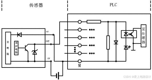
Figure 3.1.1 NPN Open Collector Output and PLC Connection (Common Point Negative)
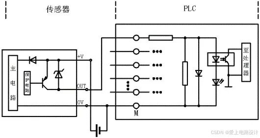
Figure 3.1.2 PNP Open Collector Output and PLC Connection (Common Point Positive)
2) NPN and PNP Type Sensors
NPN and PNP type sensors actually utilize the saturation and cutoff of transistors to output two states, which belong to switching sensors. However, the output signals are completely opposite, that is, high level and low level.PNP output is high level 1, NPN output is low level 0.
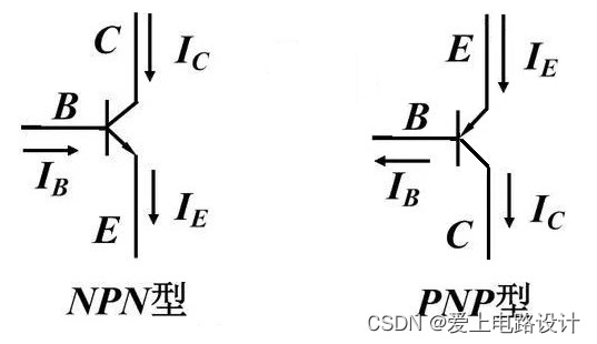
Figure 3.1.3 NPN and PNP
1) PNP has a small conduction voltage drop but low reverse voltage tolerance, while NPN has a large conduction voltage drop but high reverse voltage tolerance.
2) Schematic diagram of PNP and NPN sensor interfaces.
When the input sensor is a proximity switch, as long as the output driving force of the proximity switch is sufficient, the sink type input of the PLC can be directly connected to the output of the NPN open collector proximity switch.
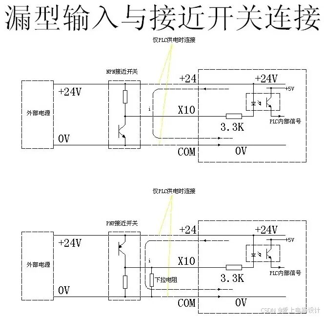
Figure 3.1.4 Sink Type Input Connected to Proximity Switch
However, when using a PNP open collector proximity switch, due to the high resistance between the output terminal of the proximity switch and 0V, it cannot provide the driving current required by the optocoupler device, so a “pull-down resistor” needs to be added.
After adding the pull-down resistor, it should be noted that the internal input signal of the PLC is opposite to the signaling state of the proximity switch, that is, when the proximity switch is signaling, the upper end of the “pull-down resistor” is 24V, and there is no current through the optocoupler device, resulting in an internal signal of “0”; when not signaling, the internal DC24V of the PLC and 0V form a current loop through the optocoupler device, current-limiting resistor, and “pull-down resistor” through the common point COM, resulting in an input of “1”.
The value of the pull-down resistor is mainly determined by the driving current of the PLC input optocoupler device and the value of the current-limiting resistor in the PLC internal input circuit. Typically, its value is 1.5kΩ to 2kΩ, and the calculation formula is: R ≤ (Ve-0.7)/Ii-Ri.
Where: R – pull-down resistor (kΩ) Ve – input power supply voltage (V) Ii – minimum input driving current (mA) Ri – PLC internal input current-limiting resistor (kΩ)
In formula 1, the conduction voltage of the LED is taken as 0.7V.
Or formula 2: R ≤ input current-limiting resistor/(minimum ON voltage/24V)]-input current-limiting resistor.
When the input sensor is a proximity switch, as long as the output driving force of the proximity switch is sufficient, the source type input of the PLC can be directly connected to the output of the PNP open collector proximity switch.
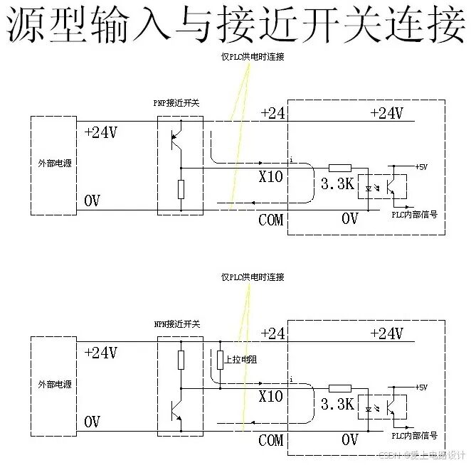
Figure 3.1.5 Source Type Input Connected to Proximity Switch
Conversely, when using an NPN open collector proximity switch, due to the high resistance between the output terminal of the proximity switch and 24V, it cannot provide the driving current required by the optocoupler device, so a “pull-up resistor” needs to be added.
After adding the pull-up resistor, it should be noted that the internal input signal of the PLC is opposite to the signaling state of the proximity switch, that is, when the proximity switch is signaling, the upper end of the “pull-up resistor” is 0V, and there is no current through the optocoupler device, resulting in an internal signal of “0”; when not signaling, the internal DC24V of the PLC and 0V form a current loop through the optocoupler device, current-limiting resistor, and “pull-up resistor” through the common point COM, resulting in an input of “1”.
The value of the pull-up resistor is mainly determined by the driving current of the PLC input optocoupler device and the value of the current-limiting resistor in the PLC internal input circuit. Typically, its value is 1.5 to 2kΩ, and its calculation formula is the same as that of the pull-down resistor.
—————-
For light curtain protection devices: Generally, PNP high-level effective state is commonly used, where the PLC input terminal is in a low-level blocking state, and the light curtain protection device continues to protect.
3.2 NPN and PNP Settings of PLC
The following figure shows the S/S settings of Mitsubishi PLC, which can be set as sink type or source type, the image is sourced from “FX3G Series – User Manual – Position Control Chapter” page 58.
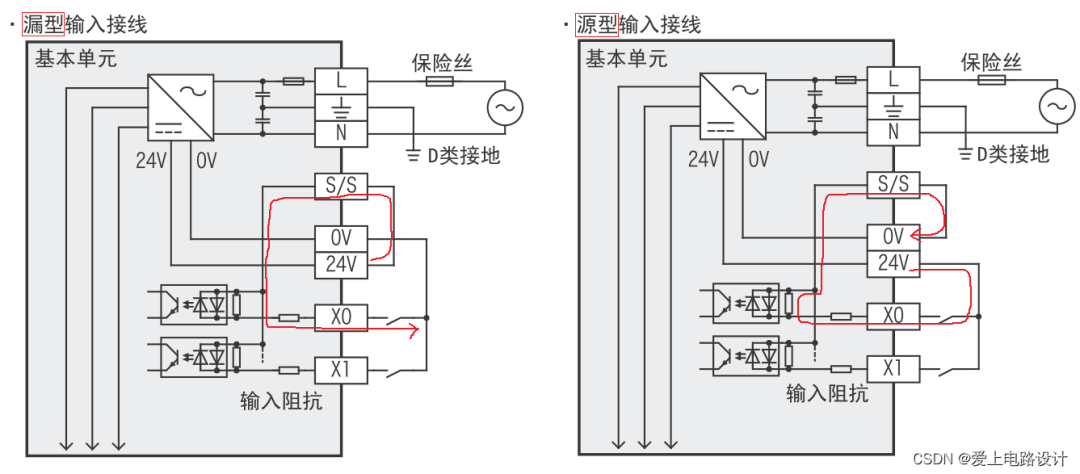
Figure 3.2.1 PLC Sink Type and Source Type Input Wiring
The internal circuit simulation is shown in Figure 3.2.2 below:
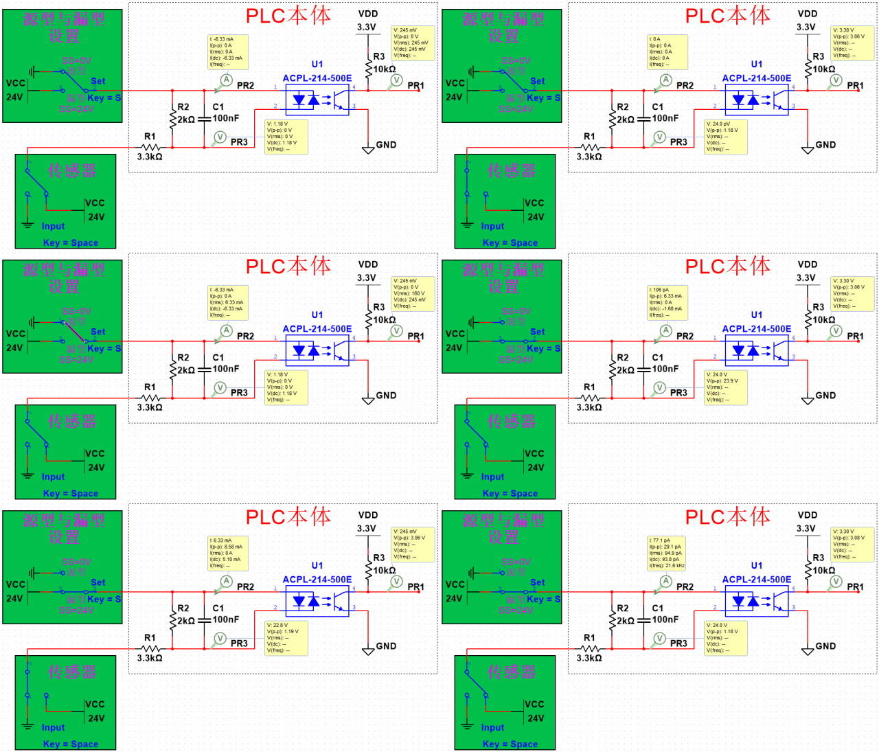
Figure 3.2.2 PLC InputMultisim Simulation
ACPL-214-500E (Electronic Component – Optocoupler) specification screenshot:
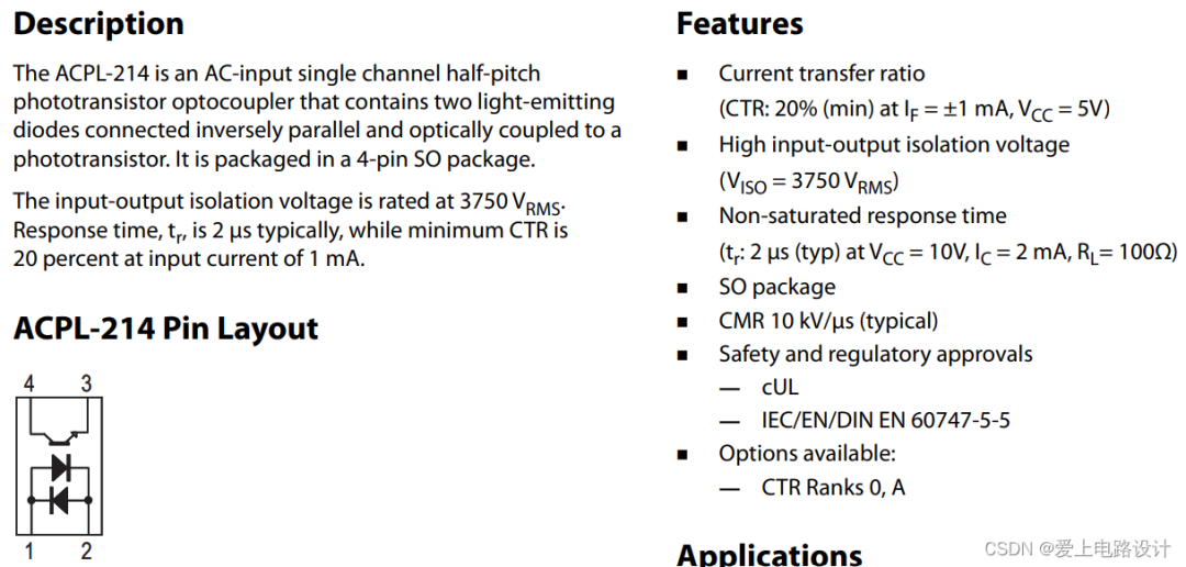
Figure 3.2.3 Excerpt from ACPL-214-500E Optocoupler Specification
4. Programming Languages
4.1 Graphical Programming
Electrical engineer style ladder diagrams, gate circuit style FBD (Function Block Diagram), flowchart style SFC (Sequence Function Chart).
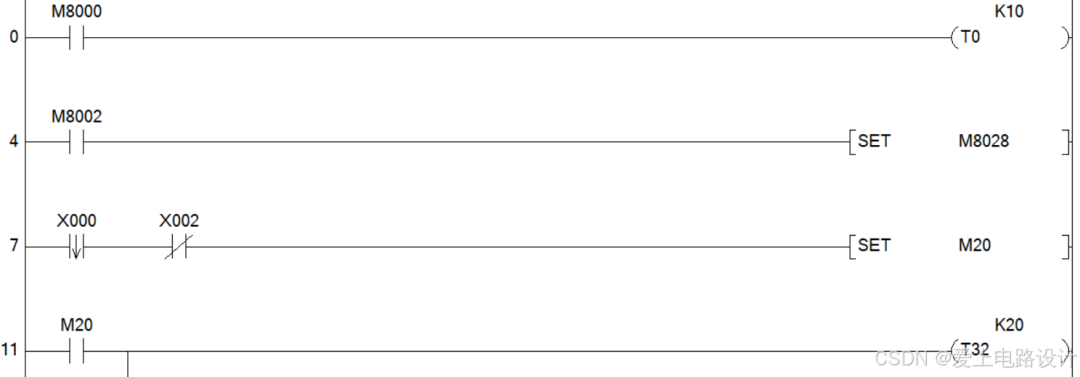
Figure 4.1.1 Ladder Diagram
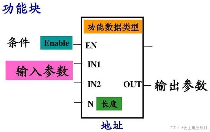
Figure 4.1.2 Siemens FBD
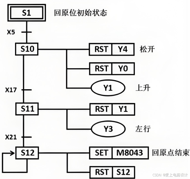
Figure 4.1.3 Mitsubishi SFC
4.2 Textual Programming
Programmer style ST (Structured Text) language (Introduction to ST Language Based on GX Works2), assembly language style instruction list IL (Instruction List).
SET(X0,Y0);RST(NOT X0,Y0);IEC1131-3 programming languages are a set of international programming language standards for industrial control systems formed based on the reasonable absorption and reference of programming languages from PLC manufacturers worldwide.
It is not only applicable to PLC systems but also to a wider range of industrial control fields, making significant contributions to the global standardization of PLC programming languages.

Mitsubishi FX Series PLC – Programming 1
Detailed Explanation of PLC Programming Ideas with Examples
Without effort, love and beauty will not be possessed..If you think it’s good, give a thumbs up!