A64 memory access instructions include floating-point and NEON scalar load/store instructions, instructions for accessing multiple memory locations, unprivileged access instructions, prefetch memory instructions, non-temporal load/store pair instructions, memory barriers and fence instructions, and synchronization primitives.

1. Floating-point and NEON Scalar Load/Store Instructions
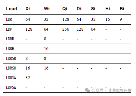
Load and store instructions can also access floating-point/NEON registers. Here, the size is determined solely by the register being loaded or stored, which can be any of the B, H, S, D, or Q registers.
Load Instructions
Store Instructions
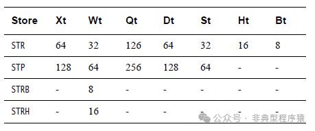
No sign extension options are available for loading into FP/SIMD registers. The addresses for such loads are still specified using general-purpose registers.
For example:
LDR D0, [X0, X1] — loads a double word from the memory address pointed to by X0 + X1 into register D0.
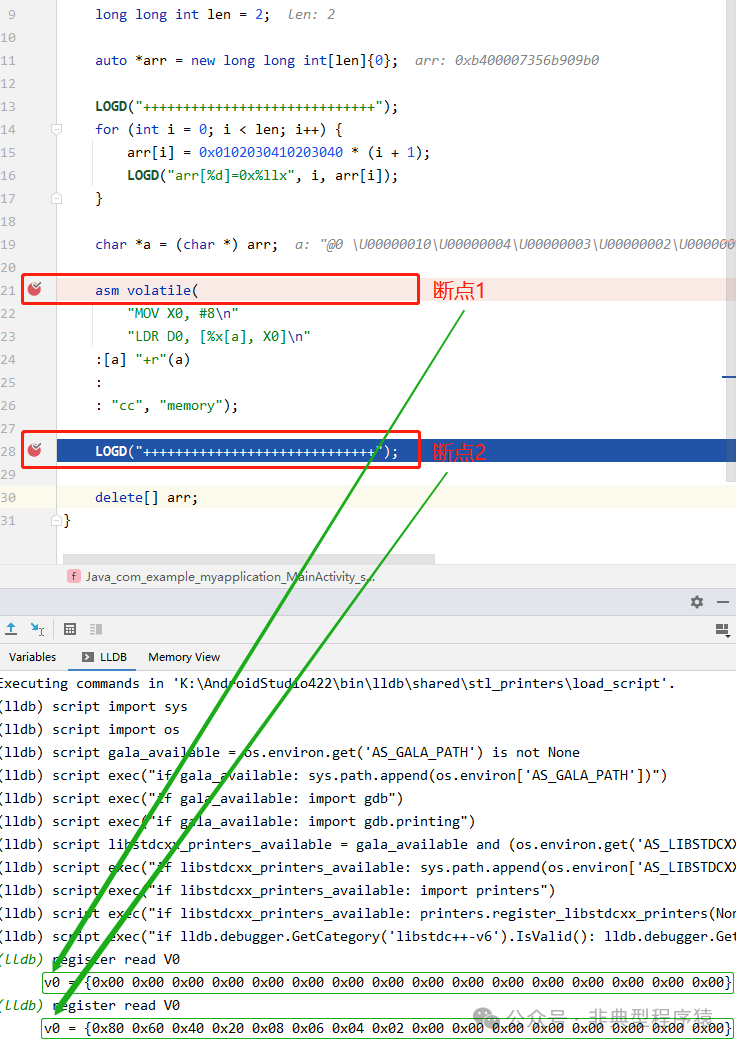
The following example shows the effect of executing the LDR D0, [%x[a], X0] instruction.
    long long int len = 2;

    auto *arr = new long long int[len]{0};

    LOGD("+++++++++++++++++++++++++++++");
    for (int i = 0; i < len; i++) {
        arr[i] = 0x0102030410203040 * (i + 1);
        LOGD("arr[%d]=0x%llx", i, arr[i]);
    }

    char *a = (char *) arr;

    asm volatile(
        "MOV X0, #8\n"
        "LDR D0, [%x[a], X0]\n"
    :[a] "+r"(a)
    :
    : "cc", "memory");

    LOGD("+++++++++++++++++++++++++++++");

    delete[] arr;
We see that the V0 register is 0 at breakpoint 1, and when it runs to breakpoint 2, it has been modified to the value of arr[1]=0x204060820406080. This is because D0 is actually the lower half of the V0 register.
Floating-point and scalar NEON loads and stores use the same addressing modes as integer loads and stores.
2. Instructions for Accessing Multiple Memory Locations
A64 does not include multiple load (LDM) or store (STM) instructions available for A32 and T32 code. In A64 code, there are load pair (LDP) and store pair (STP) instructions. Unlike A32 LDRD and STRD instructions, these can read or write any two integer registers. Data is read or written from adjacent memory locations. The addressing mode options provided for these instructions are more limited than for other memory access instructions. LDP and STP instructions can only use a base register with a scaled signed immediate value of 7 bits, with optional pre- or post-increment. Unlike 32-bit LDRD and STRD, LDP and STP can perform unaligned accesses.
| Load and Store Pair Instructions | Description |
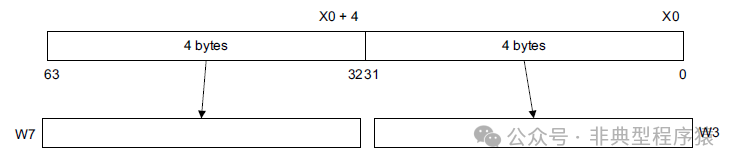
LDP W3, W7, [X0] |
Loads a word from address X0 into W3 and a word from address X0 + 4 into W7. |
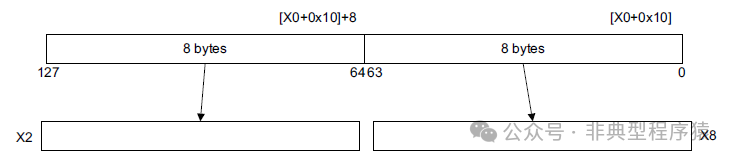
LDP X8, X2, [X0, #0x10]! |
Loads a double word from address X0 + 0x10 into X8, loads a double word from address X0 + 0x10 + 8 into X2, and adds 0x10 to X0. |
LDPSW X3, X4, [X0] |
Loads a word from address X0 into X3 and a word from address X0 + 4 into X4, sign-extending both to double word size. |
LDP D8, D2, [X11], #0x10 |
Loads a double word from address X11 into D8, loads a double word from address X11 + 8 into D2, and adds 0x10 to X11. |
STP X9, X8, [X4] |
Stores a double word from X9 to address X4 and a double word from X8 to address X4 + 8. |
LDP W3, W7, [X0] instruction illustration:
LDP X8, X2, [X0, #0x10] instruction illustration:
2.1 LDP
The load pair of registers instruction calculates the address based on the base register value and immediate offset, loads two 32-bit words or two 64-bit double words from memory, and writes them into two registers.
Post-index

32-bit (opc == 00)
LDP <Wt1>, <Wt2>, [<Xn|SP>], #<imm>
64-bit (opc == 10)
LDP <Xt1>, <Xt2>, [<Xn|SP>], #<imm>
Pre-index

32-bit (opc == 00)
LDP <Wt1>, <Wt2>, [<Xn|SP>, #<imm>]!
64-bit (opc == 10)
LDP <Xt1>, <Xt2>, [<Xn|SP>, #<imm>]!
Signed offset

32-bit (opc == 00)
LDP <Wt1>, <Wt2>, [<Xn|SP>{, #<imm>}]
64-bit (opc == 10)
LDP <Xt1>, <Xt2>, [<Xn|SP>{, #<imm>}]
<Wt1> is the 32-bit name of the first general-purpose register to be transferred, encoded in the “Rt” field.
<Wt2> is the 32-bit name of the second general-purpose register to be transferred, encoded in the “Rt2” field.
<Xt1> is the 64-bit name of the first general-purpose register to be transferred, encoded in the “Rt” field.
<Xt2> is the 64-bit name of the second general-purpose register to be transferred, encoded in the “Rt2” field.
<Xn|SP> is the 64-bit name of the general base register or stack pointer, encoded in the “Rn” field.
<imm> is the signed immediate byte offset for the 32-bit post-index and 32-bit pre-index variants: it is a multiple of 4 in the range of -256 to 252, encoded in the “imm7” field as <imm>/4. For the 32-bit signed offset variant: it is an optional signed immediate byte offset, a multiple of 4 in the range of -256 to 252, defaulting to 0 and encoded in the “imm7” field as <imm>/4.
For the 64-bit post-index and 64-bit pre-index variants: it is a signed immediate byte offset, a multiple of 8 in the range of -512 to 504, encoded in the “imm7” field as <imm>/8. For the 64-bit signed offset variant: it is an optional signed immediate byte offset, a multiple of 8 in the range of -512 to 504, defaulting to 0 and encoded in the “imm7” field as <imm>/8.
LDP Post-index
Here is an example using the LDP Post-index instruction.
    long long int len = 3;

    long long int x = 0;
    long long int y = 0;
    long long int z = 0;
    long long int w = 0;

    auto *arr = new long long int[len]{0};

    LOGD("+++++++++++++++++++++++++++++");
    LOGD("x=0x%llx y=0x%llx z=0x%llx w=0x%llx", x, y, z, w);
    for (int i = 0; i < len; i++) {
        arr[i] = 0x0102030410203040 * (i + 1);
        LOGD("arr[%d]=0x%llx", i, arr[i]);
    }

    char *a = (char *) arr;

    asm volatile(
        "LDP %x[x], %x[y], [%x[a]], #8\n"
        "LDP %x[z], %x[w], [%x[a]], #8\n"
    :[a] "+r"(a),
     [x] "+r"(x),
     [y] "+r"(y),
     [z] "+r"(z),
     [w] "+r"(w)
    :
    : "cc", "memory");

    LOGD("-----------------------------");
    LOGD("x=0x%llx y=0x%llx z=0x%llx w=0x%llx", x, y, z, w);

    delete[] arr;
It is easy to observe that the LDP %x[x], %x[y], [%x[a]], #8 instruction first loads arr[0] into the %x[x] register, then loads the value at arr + 8 (which is arr[1]) into the %x[y] register. The LDP %x[z], %x[w], [%x[a]], #8 instruction then loads the value at arr + 8 (which is arr[1]) into the %x[z] register and arr + 16 into the %x[w]. We see that LDP %x[x], %x[y], [%x[a]], #8 stored arr + 8 in %x[a] at the same time, with the address incremented only once, not twice!
The results are as follows:
2023-05-02 07:40:26.204 24915-24915/com.example.myapplication D/native-armv8a: +++++++++++++++++++++++++++++
2023-05-02 07:40:26.204 24915-24915/com.example.myapplication D/native-armv8a: x=0x0 y=0x0 z=0x0 w=0x0
2023-05-02 07:40:26.204 24915-24915/com.example.myapplication D/native-armv8a: arr[0]=0x102030410203040
2023-05-02 07:40:26.204 24915-24915/com.example.myapplication D/native-armv8a: arr[1]=0x204060820406080
2023-05-02 07:40:26.204 24915-24915/com.example.myapplication D/native-armv8a: arr[2]=0x306090c306090c0
2023-05-02 07:40:26.204 24915-24915/com.example.myapplication D/native-armv8a: -----------------------------
2023-05-02 07:40:26.204 24915-24915/com.example.myapplication D/native-armv8a: x=0x102030410203040 y=0x204060820406080 z=0x204060820406080 w=0x306090c306090c0
LDP Pre-index
Here is an example using the LDP Pre-index instruction. This modifies the LDP Post-index example slightly (changing len to 4 and changing the LDP instruction to the Pre-index format).
    long long int len = 4;

    long long int x = 0;
    long long int y = 0;
    long long int z = 0;
    long long int w = 0;

    auto *arr = new long long int[len]{0};

    LOGD("+++++++++++++++++++++++++++++");
    LOGD("x=0x%llx y=0x%llx z=0x%llx w=0x%llx", x, y, z, w);
    for (int i = 0; i < len; i++) {
        arr[i] = 0x0102030410203040 * (i + 1);
        LOGD("arr[%d]=0x%llx", i, arr[i]);
    }

    char *a = (char *) arr;

    asm volatile(
        "LDP %x[x], %x[y], [%x[a], #8]!\n"
        "LDP %x[z], %x[w], [%x[a], #8]!\n"
    :[a] "+r"(a),
     [x] "+r"(x),
     [y] "+r"(y),
     [z] "+r"(z),
     [w] "+r"(w)
    :
    : "cc", "memory");

    LOGD("-----------------------------");
    LOGD("x=0x%llx y=0x%llx z=0x%llx w=0x%llx", x, y, z, w);

    delete[] arr;
It is easy to observe that LDP Pre-index first adds 8 to the address and saves it, then loads data into the registers.
The results are as follows:
2023-05-02 07:47:37.285 26563-26563/com.example.myapplication D/native-armv8a: +++++++++++++++++++++++++++++
2023-05-02 07:47:37.285 26563-26563/com.example.myapplication D/native-armv8a: x=0x0 y=0x0 z=0x0 w=0x0
2023-05-02 07:47:37.285 26563-26563/com.example.myapplication D/native-armv8a: arr[0]=0x102030410203040
2023-05-02 07:47:37.285 26563-26563/com.example.myapplication D/native-armv8a: arr[1]=0x204060820406080
2023-05-02 07:47:37.285 26563-26563/com.example.myapplication D/native-armv8a: arr[2]=0x306090c306090c0
2023-05-02 07:47:37.285 26563-26563/com.example.myapplication D/native-armv8a: arr[3]=0x4080c104080c100
2023-05-02 07:47:37.285 26563-26563/com.example.myapplication D/native-armv8a: -----------------------------
2023-05-02 07:47:37.285 26563-26563/com.example.myapplication D/native-armv8a: x=0x204060820406080 y=0x306090c306090c0 z=0x306090c306090c0 w=0x4080c104080c100
LDP Signed offset
Here is an example using the LDP Signed offset instruction. Both LDP instructions load from fixed positions.
    long long int len = 4;

    long long int x = 0;
    long long int y = 0;
    long long int z = 0;
    long long int w = 0;

    auto *arr = new long long int[len]{0};

    LOGD("+++++++++++++++++++++++++++++");
    LOGD("x=0x%llx y=0x%llx z=0x%llx w=0x%llx", x, y, z, w);
    for (int i = 0; i < len; i++) {
        arr[i] = 0x0102030410203040 * (i + 1);
        LOGD("arr[%d]=0x%llx", i, arr[i]);
    }

    char *a = (char *) arr;

    asm volatile(
        "LDP %x[x], %x[y], [%x[a], #8]\n"
        "LDP %x[z], %x[w], [%x[a], #8]\n"
    :[a] "+r"(a),
     [x] "+r"(x),
     [y] "+r"(y),
     [z] "+r"(z),
     [w] "+r"(w)
    :
    : "cc", "memory");

    LOGD("-----------------------------");
    LOGD("x=0x%llx y=0x%llx z=0x%llx w=0x%llx", x, y, z, w);

    delete[] arr;
The results are as follows:
2023-05-02 07:59:42.287 19495-19495/com.example.myapplication D/native-armv8a: +++++++++++++++++++++++++++++
2023-05-02 07:59:42.287 19495-19495/com.example.myapplication D/native-armv8a: x=0x0 y=0x0 z=0x0 w=0x0
2023-05-02 07:59:42.287 19495-19495/com.example.myapplication D/native-armv8a: arr[0]=0x102030410203040
2023-05-02 07:59:42.287 19495-19495/com.example.myapplication D/native-armv8a: arr[1]=0x204060820406080
2023-05-02 07:59:42.287 19495-19495/com.example.myapplication D/native-armv8a: arr[2]=0x306090c306090c0
2023-05-02 07:59:42.287 19495-19495/com.example.myapplication D/native-armv8a: arr[3]=0x4080c104080c100
2023-05-02 07:59:42.287 19495-19495/com.example.myapplication D/native-armv8a: -----------------------------
2023-05-02 07:59:42.287 19495-19495/com.example.myapplication D/native-armv8a: x=0x204060820406080 y=0x306090c306090c0 z=0x204060820406080 w=0x306090c306090c0
2.2 LDPSW
Load Pair of Registers Signed Word instruction calculates the address based on the base register value and immediate offset, loads two 32-bit words from memory, sign-extends them, and writes them into two registers.
Post-index

LDPSW <Xt1>, <Xt2>, [<Xn|SP>], #<imm>
Pre-index

LDPSW <Xt1>, <Xt2>, [<Xn|SP>, #<imm>]!
Signed offset

LDPSW <Xt1>, <Xt2>, [<Xn|SP>{, #<imm>}]
<Xt1> is the 64-bit name of the first general-purpose register to be transferred, encoded in the “Rt” field.
<Xt2> is the 64-bit name of the second general-purpose register to be transferred, encoded in the “Rt2” field.
<Xn|SP> is the 64-bit name of the general base register or stack pointer, encoded in the “Rn” field.
<simm> is the optional signed immediate byte offset, in the range of -256 to 255, defaulting to 0 and encoded in the “imm9” field.
LDPSW Post-index
Here is an example using the LDPSW Post-index instruction.
    long long int len = 4;

    long long int x = 0;
    long long int y = 0;
    long long int z = 0;
    long long int w = 0;

    auto *arr = new long long int[len]{0};

    LOGD("+++++++++++++++++++++++++++++");
    LOGD("x=0x%llx y=0x%llx z=0x%llx w=0x%llx", x, y, z, w);
    for (int i = 0; i < len; i++) {
        arr[i] = 0x0102030450203040 * (i + 1);
        LOGD("arr[%d]=0x%llx", i, arr[i]);
    }

    char *a = (char *) arr;

    asm volatile(
        "LDPSW %x[x], %x[y], [%x[a]], #8\n"
        "LDPSW %x[z], %x[w], [%x[a]], #8\n"
    :[a] "+r"(a),
     [x] "+r"(x),
     [y] "+r"(y),
     [z] "+r"(z),
     [w] "+r"(w)
    :
    : "cc", "memory");

    LOGD("-----------------------------");
    LOGD("x=0x%llx y=0x%llx z=0x%llx w=0x%llx", x, y, z, w);

    delete[] arr;
The results are as follows:
2023-05-03 07:18:33.563 16309-16309/com.example.myapplication D/native-armv8a: +++++++++++++++++++++++++++++
2023-05-03 07:18:33.563 16309-16309/com.example.myapplication D/native-armv8a: arr[0]=0x102030450608070
2023-05-03 07:18:33.563 16309-16309/com.example.myapplication D/native-armv8a: arr[1]=0x2040608a0c100e0
2023-05-03 07:18:33.563 16309-16309/com.example.myapplication D/native-armv8a: -----------------------------
2023-05-03 07:18:33.563 16309-16309/com.example.myapplication D/native-armv8a: x=0xffffffffa0c100e0 y=0xffffffffa0c100e0
3. Non-temporal Load/Store Pair Instructions
A new concept in ARMv8 is non-temporal loads and stores. These are the LDNP and STNP instructions that perform reads or writes of a pair of register values. They also hint to the memory system that caching for this data is not useful. This hint does not prohibit memory system activity, such as address caching, preloading, or gathering. However, it indicates that caching is unlikely to improve performance. A typical use case might be streaming data, but note that effective use of these instructions requires a microarchitecture-specific approach.
Non-temporal loads and stores relax memory ordering requirements. In the above case, the LDNP instruction may be observed before the preceding LDR instruction, which may lead to reading from an uncertain address in X0.
For example:
LDR X0, [X3]
LDNP X2, X1, [X0] // The instruction may not load X0 at execution time
To correct the above issue, a clear load barrier is needed:
LDR X0, [X3]
DMB nshld
LDNP X2, X1, [X0]
5.1 LDNP
Load Pair of Registers with non-temporal hint calculates the address based on the base register value and immediate offset, loads two 32-bit words or two 64-bit double words from memory, and writes them into two registers.

32-bit (opc == 00)
LDNP <Wt1>, <Wt2>, [<Xn|SP>{, #<imm>}]
64-bit (opc == 10)
LDNP <Xt1>, <Xt2>, [<Xn|SP>{, #<imm>}]
Here is an example using the LDNP instruction.
    long long int len = 2;

    long long int x = 0;
    long long int y = 0;
    auto *addr = new long long int[1]{0};
    auto *arr = new long long int[len]{0};

    LOGD("+++++++++++++++++++++++++++++");
    for (int i = 0; i < len; i++) {
        arr[i] = 0x1020304050607080 * (i + 1);
        LOGD("arr[%d]=0x%llx", i, arr[i]);
    }

    char *a = (char *) arr;
    char *z = (char *) addr;

    asm(
        "STR %x[a], [%x[z]]\n"
        "LDR X0, [%x[z]]\n"
        "LDNP %x[x], %x[y], [X0, #0]\n"
    :[a] "+r"(a),
     [x] "+r"(x),
     [y] "+r"(y),
     [z] "+r"(z)
    :
    : "cc", "memory");

    LOGD("-----------------------------");
    LOGD("x=0x%llx y=0x%llx addr[0]=0x%llx", x, y, addr[0]);

    delete[] addr;
    delete[] arr;
In the example, the LDNP instruction may be observed before the preceding LDR instruction, which may lead to reading from an uncertain address. The inline assembly removes the volatile keyword, indicating that the compiler can optimize, but currently, in the author’s environment, it still runs normally without any loading disorder occurring.
The results are as follows:
2023-05-03 17:31:32.246 13498-13498/com.example.myapplication D/native-armv8a: +++++++++++++++++++++++++++++
2023-05-03 17:31:32.246 13498-13498/com.example.myapplication D/native-armv8a: arr[0]=0x1020304050607080
2023-05-03 17:31:32.246 13498-13498/com.example.myapplication D/native-armv8a: arr[1]=0x20406080a0c0e100
2023-05-03 17:31:32.246 13498-13498/com.example.myapplication D/native-armv8a: -----------------------------
2023-05-03 17:31:32.246 13498-13498/com.example.myapplication D/native-armv8a: x=0x1020304050607080 y=0x20406080a0c0e100 addr[0]=0xb400007356acf240
5.2 STNP
Store Pair of Registers with non-temporal hint calculates the address based on the base register value and immediate offset, and stores two 32-bit words or two 64-bit double words from two registers to the calculated address.

32-bit (opc == 00)
STNP <Wt1>, <Wt2>, [<Xn|SP>{, #<imm>}]
64-bit (opc == 10)
STNP <Xt1>, <Xt2>, [<Xn|SP>{, #<imm>}]
6. Memory Barriers and Fence Instructions
Both ARMv7 and ARMv8 support different barrier operations.
- Data Memory Barrier (DMB). This forces all memory accesses that are programmatically earlier to become globally visible before any subsequent accesses.
- Data Synchronization Barrier (DSB). All pending loads and stores, cache maintenance instructions, and all TLB maintenance instructions are completed before the program continues execution. DSB behaves similarly to DMB but has additional properties.
- Instruction Synchronization Barrier (ISB). This instruction flushes the CPU pipeline and prefetch buffers, causing instructions after the ISB to be fetched (or refetched) from cache or memory.
ARMv8 introduces unidirectional barriers associated with the release consistency model. These are called Load-Acquire (LDAR) and Store-Release (STLR), and are address-based synchronization primitives. These two operations can be paired to form a complete barrier. These instructions only support base register addressing and do not provide offsets or other types of indexed addressing.
7. Synchronization Primitives
Both ARMv7-A and ARMv8-A architectures support exclusive memory access. In A64, this is the Load/Store Exclusive (LDXR/STXR) pair.
The LDXR instruction loads a value from a memory address and attempts to silently claim an exclusive lock on that address. The Store-Exclusive instruction will only write a new value to that location if it successfully acquires and holds the lock. LDXR/STXR pairs are used to construct standard synchronization primitives, such as spinlocks. A paired set of LDXRP and STXRP instructions is provided to allow code to automatically update across two registers. Options for byte, half-word, word, and double-word are available. Like the Load-Acquire/Store-Release pairs, only base register addressing is supported, with no offsets.
The CLREX instruction clears the monitor, but unlike ARMv7, an exception entry or return also clears the monitor. The monitor may also be falsely cleared for reasons unrelated to the application, such as cache eviction. Software must avoid any explicit memory accesses, system control register updates, or cache maintenance instructions between paired LDXR and STXR instructions.
There are also a pair of dedicated Load-Acquire/Store-Release instructions called LDAXR and STLXR.
References
1. “ARMv8-A Programmer’s Guide”
2. “Arm® A64 Instruction Set Architecture Armv8, for Armv8-A architecture profile”
Non-typical Programmer–☆ Link Coder Community ☆–Welcome to followRemember to likeand recommendto share with more people