Point ”Jinan CNC Mould Technology Research Institute” is pinned for attention
Industry frontiers, mechanical videos, CNC processing technology, 3D printing, industrial robots, production processes, molds, machine tools, and other cutting-edge information are waiting for you here!
Summary of Mitsubishi Communication Methods
1. N:N Network Communication
1. Communication Solutions
Data transmission using FX3U, FX2N, FX2NC, FX1N, and FX0N programmable controllers can be established on an N:N basis. Using this network communication, they can link data within a small-scale system.
2. Related Flags and Data Registers
For FX1N/FX2N/FX2NC/FX3U series programmable controllers, use internal auxiliary relays for N:N network communication, where:
M8038 is used to set network parameters;
M8183 is ON during communication errors at the master site;
M8184 to M8190 are ON when errors occur at slave sites (the first slave site is M8184, the seventh slave site is M8190);
M8191 is ON during communication with other sites;
Data register D8176 sets the site number, 0 for the master site, 1 to 7 for slave site numbers;
D8177 sets the total number of slave sites, with a value of 1 for one slave site and 2 for two slave sites;
D8178 sets the refresh range, 0 for mode 0 (default value), 1 for mode 1, 2 for mode 2;
D8179 sets the communication retry count for the master site, with values from 0 to 10;
D8180 sets the communication residency time between the master and slave sites, with values from 5 to 255, corresponding to 50 to 2550 ms.
Case Study
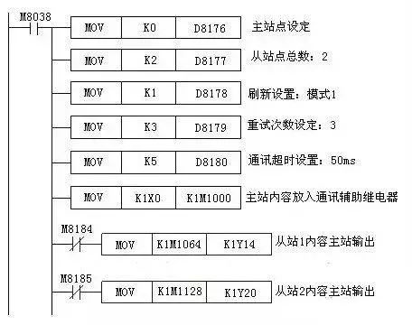
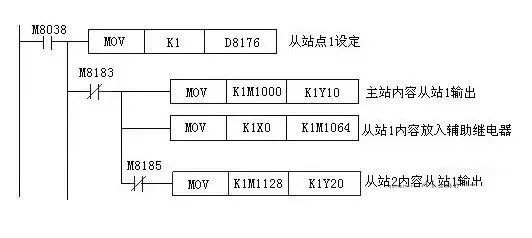
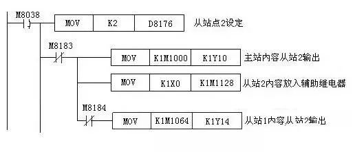
The system has three sites, including one master site and two slave sites, where each site’s programmable controller is connected to an FX2N-485-BD communication board, connected by a single twisted pair cable. The refresh range is set to mode 1, retry count is set to 3, and communication timeout is set to 50 ms. The system requirements are:
(1) The input points X0 to X3 of the master site output to the output points Y10 to Y13 of slave sites 1 and 2;
(2) The input points X0 to X3 of slave site 1 output to the output points Y14 to Y17 of the master site and slave site 2;
(3) The input points X0 to X3 of slave site 2 output to the output points Y20 to Y23 of the master site and slave site 1;
The ladder diagram for the master site is as follows:
The ladder diagram for slave site 1 is as follows:
The ladder diagram for slave site 2 is as follows:
2. Parallel Link Communication
1. Parallel Communication Solutions
Data transmission using FX3U, FX2N, FX2NC, FX1N, FX, and FX2C programmable controllers is completed on a 1:1 basis using 100 auxiliary relays and 10 data registers. Data transmission for FX1S and FXON is done using 50 auxiliary relays and 10 data registers.
2. Usage Method
When two FX series programmable controllers each have a communication module installed, they can be connected with a single twisted pair cable. During programming, set the master and slave stations, and use special relays to automatically transfer data between the two programmable controllers, making data communication connection very easy. The settings for master and slave stations are done using M8070 and M8071, and parallel connections have general and high-speed modes, identified by M8162.
3. Communication Example
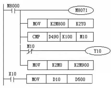
In the parallel communication system, the control requirements are as follows:
(1) The ON/OFF status of the master site’s input X0 to X7 is output to the slave site’s Y0 to Y7;
(2) When the calculation result of the master site (D0+D2) is greater than 100, the slave’s Y10 is ON;
(3) The ON/OFF status of the slave site’s M0 to M7 is output to the master site’s Y0 to Y7;
(4) The value of D10 from the slave site is used to set the timer in the master site;
The ladder diagram for the master site is as follows:
3. Computer Link
The programmer interface of programmable controllers is generally RS-422 or RS-485, while the serial communication interface of computers is RS-232C. When exchanging information between programming software and programmable controllers, a dedicated programming cable or communication adapter with the appropriate interface circuit is required. To transfer programs between programming software and FX series PLCs, the SC-09 programming cable is used.
4. Unprotocol Communication
Most programmable controllers have a type of serial port unprotocol communication instruction, such as the RS instruction of the FX series, which is used for communication between programmable controllers and host computers or other RS-232C devices. This communication method is the most flexible, allowing user-defined communication specifications between programmable controllers and RS-232C devices. However, the programming workload for programmable controllers is relatively large, and the requirements for programmers are high. If the communication specifications used by devices from different manufacturers differ, even if the physical interface is RS-485, they cannot be connected to the same network; in this case, one device will occupy a communication interface of the programmable controller.
Data communication can be completed using various RS232C units, including personal computers, barcode readers, and printers, through unprotocol communication, which is accomplished using RS instructions or a FX2N-232IF special function module.
5. Optional Programming Port Communication
Current programmable terminal products (such as Mitsubishi’s GOT-900 series graphic operation terminal) generally work with programmable controllers from multiple manufacturers. Similar to configuration software, the communication program between programmable terminals and programmable controllers does not need to be written by the user. When configuring the screens for the programming terminal, it is only necessary to specify the element numbers (such as buttons, indicators) corresponding to the programmable controller’s programming components, and the data exchange between the two is automatically completed.
For FX3U, FX2N, FX2NC, FX1N, and FX1S series programmable controllers, when the port is connected to FX2N-232-BD, FXON—32ADP, FX1N—232—BD, or FX2N-422—BD, it can support a programming protocol.
6. Q Series PLC Communication
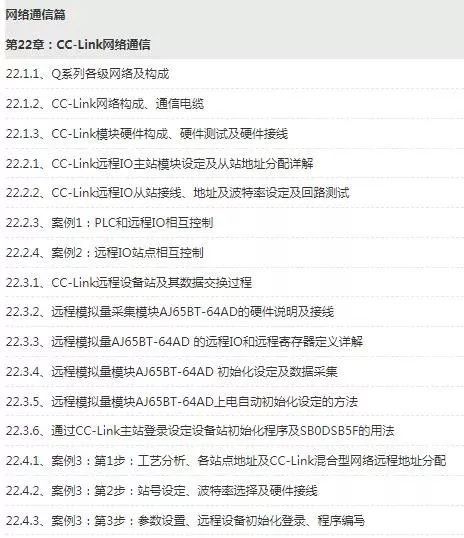
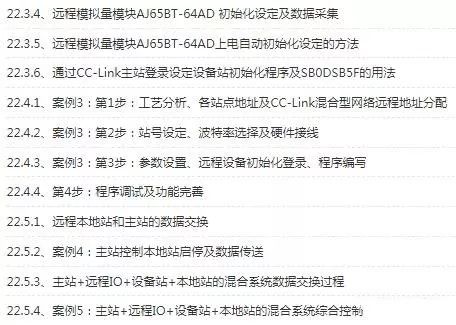
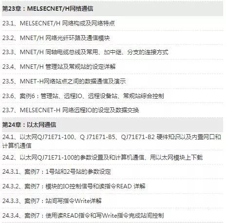
Detailed explanations about Mitsubishi Q series CC-Link network communication, MELSECNET/H network communication, Ethernet communication, etc., can be found in the Q series tutorials from 【Longfeng PLC and Robot Intelligent Training Institute】!
The directory for the communication section is as follows:
Produced by the New Media Center of Jinan CNC Mould Technology Research Institute
End
Jinan CNC Mould Technology Research Institute
On-the-job training base for college graduates——Jinan CNC Mould Technology Research Institute has been mainly engaged inCAD/CAM advanced programming, UG five-axis programming, CNC machine repair, UG mold design, reverse modeling, industrial robots, 3D printing, etc. pre-job training for many years. One-time registration for lifelong learning, during the training period, teachers conduct periodic tests to fully control students’ learning progress, with small class teaching, one-on-one tutoring, and a combination of theory and practice until mastery. After completion, free employment recommendations are provided. The research institute provides long-term technical support and employment services for students. All teachers and students of the Jinan CNC Mould Technology Research Institute welcome your visit and learning. The research institute is currently located at 1 Shiji Avenue, Zhangqiao District, Jinan City,2510.
Consultation Hotline: 0531-85708996
 Here | Read Electric Institute | Read Life
In Jiyan | Learn Skills | Read Life