Produced by | Furui Microelectronics

Overview of Virtualization
1.1 Drivers and Advantages
Virtualization is a widely used technology that supports nearly all modern cloud computing and enterprise infrastructure. Developers can run multiple operating systems on a single machine based on virtualization capabilities, allowing software testing without risking damage to the primary computing environment. Virtualization brings many features to chips and infrastructure, including good isolation, accessibility of different resources, workload balancing of the same resource, and isolation protection.
For automotive chips, especially cockpit domain SoCs, the current development trend is to save costs by increasing integration. Therefore, multiple operating systems corresponding to physical resources will be integrated on the same SoC chip, and these resources need to coexist in a virtualized environment with safe isolation. Specifically, the requirements and challenges faced by in-vehicle SoC virtualization include:
-
Isolation between at least three domains with different security requirements and heterogeneous operating systems, where the domain running RTOS needs to meet ASIL-D safety level requirements, the domain running QNX or lightweight Linux needs to meet ASIL-B safety level requirements for the instrument domain, and the information and entertainment domain system running Android or HarmonyOS.
-
Accessibility and workload balancing of critical resources, including memory, CPU threads, etc., especially when the GPU or NPU is handling massive workloads. Under power constraints and memory capacity limitations, virtualization dynamically ensures resource availability and flexibility.
1.2 Introduction to Hypervisor
The hypervisor is the core supporting component of virtualization functionality. The hypervisor is mainly responsible for handling virtual machine traps and managing actual physical resources. Hypervisors can be divided into two main categories:
-
Native standalone hypervisor, commonly referred to as Type 1 hypervisor. This type of hypervisor runs with the highest privileges, controlling and managing all physical resources. During the operation of this type of hypervisor, resource management and scheduling functions related to each virtual machine can be offloaded to the operating system of that virtual machine, allowing the management program to focus on virtualization-related functions. Typical examples of this type of hypervisor include QNX Hypervisor and Xen Hypervisor.
-
Host operating system embedded hypervisor extension, generally referred to as Type 2 hypervisor, where basic management functions can be achieved through the host operating system, and the hypervisor extension focuses solely on virtualization support, working in conjunction with the host operating system to achieve virtualization functionality. A typical example of this type of hypervisor is Linux KVM.
Corresponding to the ARM exception handling architecture, the application or user space of the virtual machine operating system is typically at EL0 security level. The kernel space of the virtual machine operating system is at EL1 security level. To support virtualization extensions, EL2 security level is introduced. The specific security levels are detailed in the following diagram:
-
For Type 1 hypervisor: the user space of the virtual machine operating system is at EL0 security level, the kernel space of the virtual machine operating system is at EL1 security level, and the standalone hypervisor is at EL2 security level.
-
For Type 2 hypervisor: both the user space of the virtual machine operating system and the user space of the host operating system are at EL0 security level, while the kernel space of the virtual machine operating system is at EL1 security level. The kernel space of the host operating system with hypervisor extension is at EL2 security level.
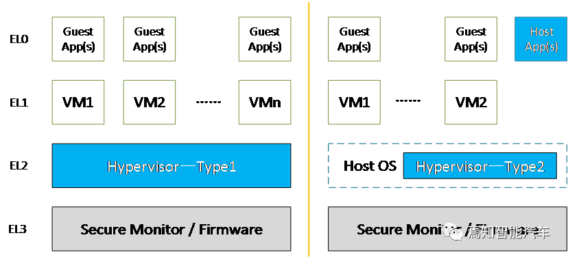 Figure 1. Types of Hypervisors and Corresponding ARM Exception Handling Levels
Without loss of generality, subsequent chapters will introduce the main issues and solutions of current virtualization using QNX Hypervisor-related software implementations and hardware implementations based on ARMv8.0 architecture as typical examples. Based on the functional division of virtualization scenarios, the current mainstream cockpit SoC virtualization can be roughly divided into three categories:
-
CPU virtualization for VM management and execution;
-
Memory virtualization for memory space separation and management;
-
Device virtualization for device configuration and management.
2.1 Overview of CPU Virtualization
The CPU or processor can provide an abstract virtual processor for VMs and execute the corresponding instructions of specific VMs. Generally, the hypervisor runs directly on the physical CPU, occupying physical resources and directly using the physical CPU’s ISA. The virtual machine operating system occupies relevant resources and executes related instructions based on the abstraction of the virtual processor; except for actions requiring higher privileges, most scenarios can directly use physical CPU resources and the ISA of the physical CPU.
The cooperative management of hypervisors and VMs is achieved through the virtual machine trap mechanism, which typically occurs when a VM or application needs higher privileges to execute. In the ARM architecture, as described above, the exception handling levels for virtualization, VMs and applications can have at most EL1 privileges. Therefore, executing disallowed instructions will trigger a virtual machine trap. The detailed process is as follows:
-
Under normal circumstances, VMs run their instructions on the physical CPU, just like without a hypervisor;
-
When the virtual machine operating system or application attempts to execute an instruction beyond its execution privileges, it triggers a virtual machine trap, and the virtual machine operating system performs a context switch to the hypervisor program;
-
After the virtual machine trap occurs, the hypervisor takes over the scene and saves the context of the virtual machine, then processes the tasks initiated by the virtual machine operating system;
-
When the hypervisor completes the task, it restores the VM’s context and returns execution privileges to the VM.
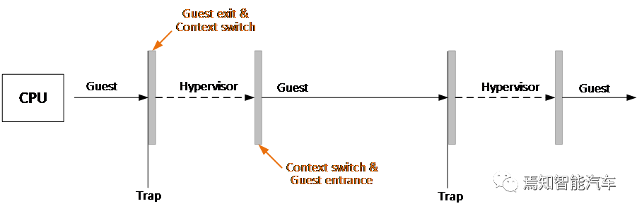 Figure 2. Virtual Machine Trap Mechanism and Processing Flow
Virtual machine abstraction and trap handling mechanisms will be further introduced in subsequent chapters on QNX Hypervisor and ARM architecture.
Figure 2. Virtual Machine Trap Mechanism and Processing Flow
Virtual machine abstraction and trap handling mechanisms will be further introduced in subsequent chapters on QNX Hypervisor and ARM architecture.
2.2 QNX Virtual Machine and Virtual Processor Support
The detailed hierarchy of resources and components in the QNX Hypervisor software architecture is shown in the diagram below. From the perspective of the hypervisor as an operating system, each VM needs to register in the user space of the hypervisor operating system by instantiating a qvm process.When configuring a certain VM, a corresponding qvm process is created and configured according to the specifications to specify the components of that VM, including virtual virtual processors (vCPU), virtual devices, memory management page table configurations, etc.
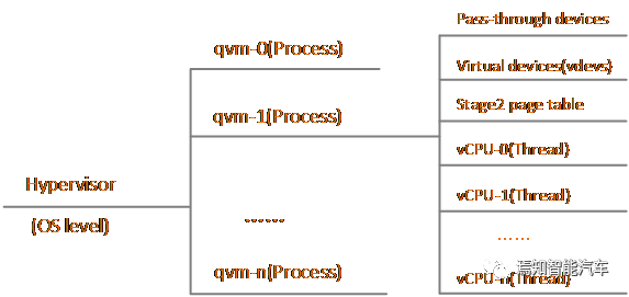 Figure 3. Resource Hierarchy of QNX Hypervisor
During the normal operation of the hypervisor, the qvm process instance needs to perform the following operations:
When a qvm process is instantiated, multiple vCPU threads, virtual device lists, and Stage 2 page tables are instantiated within the process, used for application thread abstraction, virtual device abstraction, and memory virtualization abstraction, respectively.For vCPU abstraction, the QNX Hypervisor follows a priority-based vCPU sharing model, where the priorities include qvm process priority and vCPU thread priority.In the hypervisor running rules, the relative priority of the qvm process and the hierarchical priority of the vCPU scheduling threads within the qvm process determine which vCPU can access the physical CPU.However, during the mapping process and subsequent execution, the contents and data running in the VM are completely opaque to the hypervisor.The hypervisor only ensures that when sharing the physical CPU based on vCPU priority and scheduling strategies, higher-priority vCPUs will always preempt lower-priority vCPUs.The virtual device lists and Stage 2 page tables will be introduced in subsequent chapters.
Figure 3. Resource Hierarchy of QNX Hypervisor
During the normal operation of the hypervisor, the qvm process instance needs to perform the following operations:
When a qvm process is instantiated, multiple vCPU threads, virtual device lists, and Stage 2 page tables are instantiated within the process, used for application thread abstraction, virtual device abstraction, and memory virtualization abstraction, respectively.For vCPU abstraction, the QNX Hypervisor follows a priority-based vCPU sharing model, where the priorities include qvm process priority and vCPU thread priority.In the hypervisor running rules, the relative priority of the qvm process and the hierarchical priority of the vCPU scheduling threads within the qvm process determine which vCPU can access the physical CPU.However, during the mapping process and subsequent execution, the contents and data running in the VM are completely opaque to the hypervisor.The hypervisor only ensures that when sharing the physical CPU based on vCPU priority and scheduling strategies, higher-priority vCPUs will always preempt lower-priority vCPUs.The virtual device lists and Stage 2 page tables will be introduced in subsequent chapters.
2.3 ARM Virtual Machine and Virtual Processor Support
The trap mechanism in the ARM architecture is implemented through exception handling.As mentioned above, the application or user space of the virtual machine operating system is typically at EL0 security level.The kernel space of the virtual machine operating system is at EL1 security level.The hypervisor is at EL2 security level.As shown on the left side below, when a VM or application instruction exceeds the EL1 security level, an exception trap is sent to the hypervisor at EL2 to handle the exception, then returns to the VM at EL1 security level through context switching.
The right diagram illustrates a CPU capturing the WFI processing. Executing the Wait For Interrupt (WFI) instruction usually causes the physical CPU to enter a low-power state. By injecting the TWI signal, if HCR_EL2.TWI==1 is satisfied, executing WFI at EL0 or EL1 will result in an exception and trap to EL2 for processing. In this example, the VM typically executes WFI in an idle loop, while the hypervisor can capture such trap actions and schedule different vCPUs to this physical CPU instead of directly entering a low-power state.
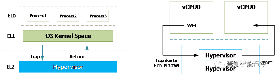 Figure 4. Trap Mechanism and WFI Trap Example
In the ARM architecture, vCPU generally represents a virtual processing unit, and each vCPU needs to instantiate a corresponding vCPU thread in the hypervisor.The VM corresponds to an instantiated qvm process in the hypervisor, which will contain one or more vCPU threads.
Figure 4. Trap Mechanism and WFI Trap Example
In the ARM architecture, vCPU generally represents a virtual processing unit, and each vCPU needs to instantiate a corresponding vCPU thread in the hypervisor.The VM corresponds to an instantiated qvm process in the hypervisor, which will contain one or more vCPU threads.
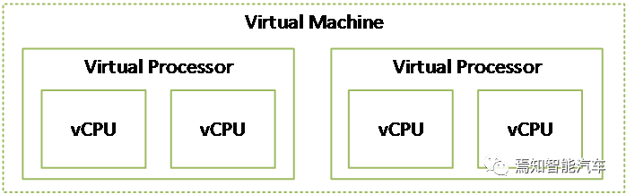 Figure 5. Hierarchical Relationship of ARM Virtual Machines and Virtual Processors
Memory Virtualization
3.1 Overview of Memory Virtualization
Memory virtualization, combined with CPU virtualization, can ensure that all VMs have independent memory spaces and are strictly isolated according to permissions.The key requirement for memory virtualization is address management, configuring and controlling each VM’s access to physical memory according to context.
Memory virtualization is typically implemented in conjunction with memory allocation and release management. From a hardware implementation perspective, typical memory virtualization is achieved through controlling two-level address translation. The memory allocation and release mechanisms for the hypervisor and VMs are similar to those of typical operating systems, using hierarchical page tables to implement memory management.
3.2 ARM Memory Management System
The ARM architecture adopts a two-level address translation mechanism based on page tables.Generally, the first-level translation converts the virtual address (VA) to an intermediate physical address (IPA), and this level of address translation is managed and controlled by the operating system.The second-level address translation converts the intermediate physical address (IPA) to the physical address (PA), and this level of address translation is managed and controlled by the hypervisor.These two stages of translation are independent and do not interfere with each other.As shown in Figure 6, consecutive virtual page addresses can map to discrete addresses in intermediate physical pages, while discrete addresses in intermediate physical pages can map to consecutive physical page addresses.
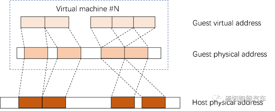 Figure 6. Two-Level Address Translation Mechanism
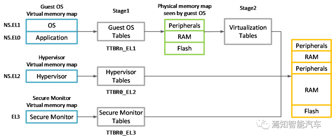
The following diagram shows a typical two-level address space in the ARMv8 architecture. The virtual address space mainly represents:
Figure 6. Two-Level Address Translation Mechanism
The following diagram shows a typical two-level address space in the ARMv8 architecture. The virtual address space mainly represents:
-
The virtual memory mapping space of the virtual machine operating system located in non-secure EL0/EL1 security levels;
-
The virtual memory mapping space of the hypervisor located in non-secure EL2 security level;
-
The virtual memory mapping space of the secure monitor located in EL3 security level.
These virtual address spaces are independent of each other, and each memory space has independent configuration and page tables.The illustrated two-level page table can comprehensively support memory virtualization functions, where the Stage 1 virtual machine operating system page table can convert virtual addresses to intermediate physical addresses, including serial port device addresses, memory addresses, and storage device addresses, while the Stage 2 virtualization page table, combined with the hypervisor page table and secure monitor page table, can convert intermediate physical addresses to valid physical addresses.
Figure 7. Typical Two-Level Address Space in ARMv8
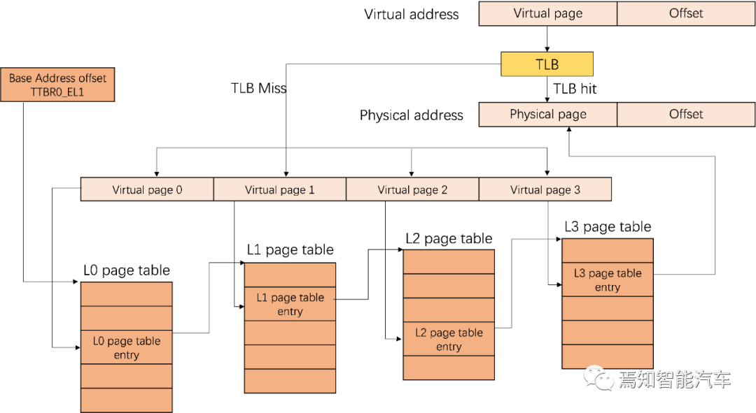
In the AArch64 architecture, physical addresses are typically 48 bits, and page table sizes are usually 4KB or 64KB. To avoid excessive page table space, a four-level page table division is usually adopted to query page table entries based on address segments. The following diagram shows an example of a four-level page table and first-level address translation; specific content will not be elaborated on in this article.
Figure 8. AArch64 Four-Level Page Table and First-Level Address Translation Example
Device Virtualization
4.1 Overview of Device Virtualization
The concept of Device in virtualization can be summarized as accessible memory devices in the system other than the processors running the hypervisor and VMs. In cockpit chips, typical types of devices can be summarized as:
-
Software simulated virtual devices: Capture native drivers through software simulation or hardware virtualization methods, and then simulate the behavior of virtual devices within the hypervisor, with all VMs interacting with the device through the management program traps;
-
Para-virtualized devices: Simulate an actual physical device for all VMs, allowing all VMs to perform batch calls to the device through a single trap;
-
Passthrough devices: Completely exclusive to specific VMs in the virtualized environment;
-
Shared devices: Can be used by one VM or one or more VMs and the hypervisor itself.
Subsequent chapters will detail the specific implementations of device virtualization in QNX Hypervisor and the support for device virtualization under the ARM architecture.
4.2 QNX Device Virtualization Support
Devices in QNX Hypervisor can be summarized as:
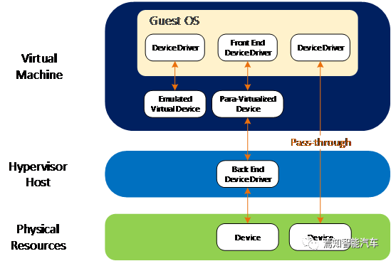
As mentioned earlier, when configuring and instantiating qvm processes for VMs, QNX Hypervisor needs to configure physical devices and virtual devices (vdev) for the qvm processes and VMs. The following diagram illustrates the support for different types of device virtualization in QNX Hypervisor.
Figure 9. Device Virtualization Support in QNX Hypervisor
For passthrough devices, VMs have direct and exclusive access rights, and the hypervisor host operating system will be bypassed. The driver for these passthrough devices will also be directly owned by the VM. For passthrough devices, the hypervisor only needs to route interrupts from the physical device directly to the corresponding VM and pass all signals from the VM directly to the corresponding device. All interactions occur between the VM and the device, and the hypervisor needs to recognize and allow interrupts from the device and signals from the VM. Typical examples of passthrough devices include PCIe, Ethernet, etc.
For shared devices, these devices can be used by multiple guests, with shared memory being a typical example. QNX Hypervisor supports two different types of device sharing: reference sharing and intermediary sharing:
For virtual devices, QNX Hypervisor supports fully virtualized and para-virtualized devices to isolate direct communication between physical devices on the system:
-
Fully virtualized devices/software simulated virtual devices: Virtual devices that simulate actual physical devices for VMs. When using such devices, VMs do not need to know they are running in a virtualized environment. Depending on the type of physical device, fully virtualized devices can handle all transactions themselves or act as intermediaries between VMs and actual physical devices. Typical examples include interrupt controllers (GIC), timers, etc.
-
Para-virtualized devices: Compared to fully virtualized devices, para-virtualized devices can handle device calls in batches through a single trap, thereby improving efficiency and reducing the overhead introduced by virtualization. QNX Hypervisor supports para-virtualized devices based on the VirtIO 1.0 standard, including typical block devices, I/O devices, consoles, GPUs, DPUs, ISPs, etc.
4.2 ARM Device Virtualization Support
The ARM architecture provides multifaceted support for device virtualization, with the main mechanisms including the System Memory Management Unit (SMMU) and the virtualization-supporting interrupt controller (GIC).
For devices other than processors in SoC systems, especially DMA controllers or devices with DMA controllers, when allocated by VMs in a virtualization scenario, address translation and OS-level memory protection can be ensured through the SMMU. The left diagram shows a DMA controller without virtualization support from the operating system’s perspective. The DMA controller will be programmed through the driver in the host operating system’s kernel space, which will configure the physical address for DMA based on the MMU unit. However, in a virtualized environment, from the perspective of a specific VM, passthrough DMA can only perform address translation based on the first-level MMU corresponding to that VM, thus only configuring intermediate physical addresses. Therefore, the right diagram shows the SMMU supporting virtualization for the DMA controller, allowing the VM to directly configure passthrough DMA. All memory accesses can be converted from IPA to PA through the SMMU programmed by the management program host, ensuring that both the VM and DMA operate based on IPA for a unified perspective.
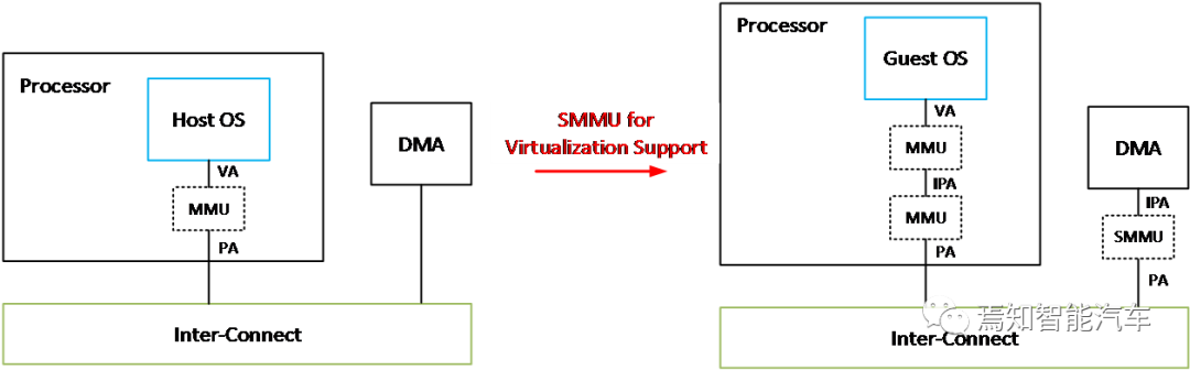 Figure 10. SMMU Support for Device Virtualization in ARM Architecture
Starting from ARM GICv2, as shown in the diagram below, the GIC can issue physical and virtual interrupt signals by providing physical CPU interfaces and virtual CPU interfaces. From the GIC’s functionality perspective, these two interfaces are the same, with the distinction being that one issues physical interrupt signals while the other issues virtual interrupt signals. The hypervisor can map the virtual CPU interface to the VM, allowing software within that VM to communicate directly with the GIC. The advantage of this mechanism is that the hypervisor only needs to set up the virtual interface without needing to adopt a fully virtualized approach to support the GIC. This can reduce the number of interrupt traps and thereby decrease the overhead of interrupt virtualization.
Figure 10. SMMU Support for Device Virtualization in ARM Architecture
Starting from ARM GICv2, as shown in the diagram below, the GIC can issue physical and virtual interrupt signals by providing physical CPU interfaces and virtual CPU interfaces. From the GIC’s functionality perspective, these two interfaces are the same, with the distinction being that one issues physical interrupt signals while the other issues virtual interrupt signals. The hypervisor can map the virtual CPU interface to the VM, allowing software within that VM to communicate directly with the GIC. The advantage of this mechanism is that the hypervisor only needs to set up the virtual interface without needing to adopt a fully virtualized approach to support the GIC. This can reduce the number of interrupt traps and thereby decrease the overhead of interrupt virtualization.
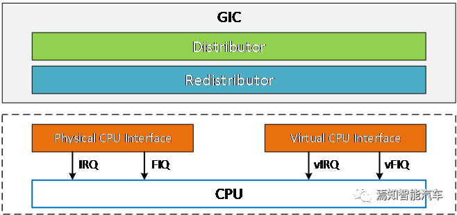 Figure 11. GIC Support for Device Virtualization in ARM Architecture
Conclusion
Virtualization is rapidly becoming a key technology in modern in-vehicle software architecture, especially as cockpit SoCs face challenges of safety isolation, flexibility, and high utilization. The combination of hypervisor software and hardware virtualization extensions can make the virtualization features in cockpit scenarios more efficient and secure.
Welcome to all angel round companies in the automotive industry chain (including the electrification industry chain),Around companies to join the group (Friendly connection including top institutions among 500 automotive investment institutions; A selection of high-quality projects will be presented to existing institutions based on themes); There are communication groups for leaders of scientific and technological innovation companies , automotive industry complete vehicles, automotive semiconductors, key parts, new energy vehicles, intelligent connected vehicles, aftermarket, automotive investment, autonomous driving, vehicle networking, and dozens of other groups. Please scan the administrator’s WeChat to join the group (Please indicate your company name)