ver0.3
Introduction
In previous articles, we introduced the ARM architecture’s interrupt controller GIC, which maintains a state machine for each interrupt signal. This interrupt state machine supports four states: Inactive, Pending, Active, and Active and Pending. The GIC maintains the status of each signal through internal registers and performs state transitions under relevant trigger conditions. In the brief yet crucial lifespan of an interrupt signal, they must all be managed by the GIC’s interrupt state machine. Everything seems perfect so far, but please hold the champagne for a moment and consider the following scenario: how do we handle these interrupt signals in specific situations, especially when multiple interrupt signals arrive at the GIC simultaneously? When one interrupt signal has already been acknowledged, and a more urgent interrupt signal arrives, how should the CPU respond? In this article, we will discuss these scenarios and the interrupt priority and preemption mechanisms provided by ARM in the current GIC infrastructure design. Additionally, some foundational knowledge is required; I recommend reading the following articles to get a feel for the topic:
(1) [V-02] Basics of Virtualization – CPU Architecture (Based on AArch64)
(2) [V-05] Basics of Virtualization – Exception Model (AArch64)
(3) [A-25] ARMv8/v9 GIC System Architecture (Hardware Fundamentals of Interrupts)
(4) [A-26] ARMv8/v9 GIC Interrupt Types
(5) [A-27] ARMv8/v9 GIC Core Components (Fundamental Components of Interrupt Programming)
(6) [A-28] ARMv8/v9 GIC Interrupt Signal Routing Mechanisms and Strategies
(7) [A-29] ARMv8/v9 GIC – Security Architecture Design of the Interrupt Subsystem (Security/FIQ/IRQ)
(8) [A-30] ARMv8/v9 GIC – Interrupt Handling (Interrupt State Machine/Interrupt Lifecycle)
Body
1.1 Background of Interrupt Priority
To understand the background of interrupt priority, we first need to clarify a concept: resources, as shown in Figure 1-1.
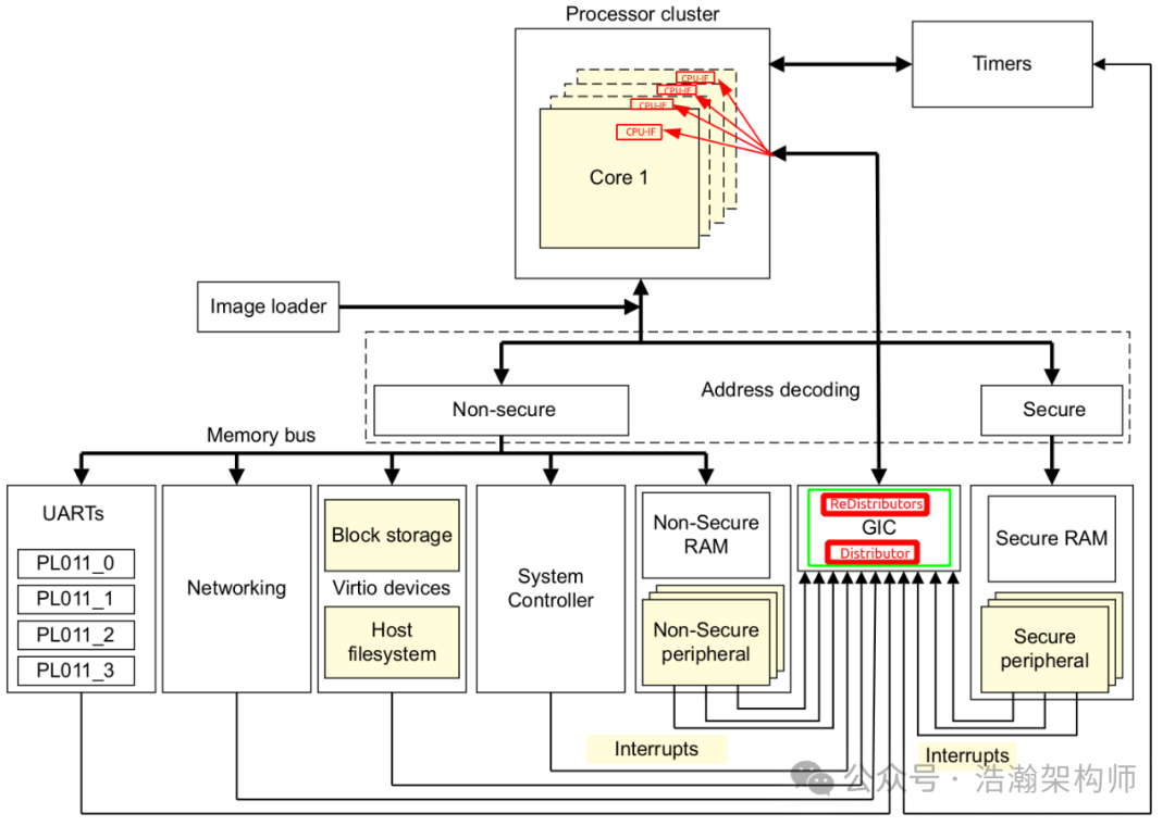
Figure 1-1 ARMv8a System Block Diagram
The above diagram is a classic High-Level SOC architecture diagram from the ARM manual. The number of external devices alone is quite considerable. From the user’s perspective, all devices on the board are resources. A keyboard can be connected via a serial port, a network card can download movies, and an amplifier can provide an ultimate music experience. From the device’s perspective, both external and internal devices rely on the CPU’s command to function; for example, allocating appropriate memory space, preparing data through the CPU, and issuing commands via the bus. When various IPs need resources, they must report to the CPU, and the most efficient channel for this is the interrupt mechanism. Let’s take a look at the CPU’s inner world from the device’s perspective, as shown in Figure 1-2.
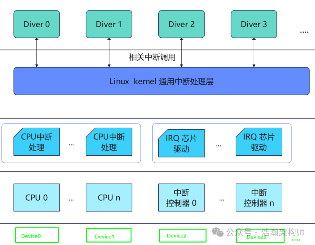
Figure 1-2 High-Level Interrupt Handling Software Framework
The purpose of a device sending an interrupt message is to prompt the CPU to notify its driver that data is ready to be loaded at a certain address space, a previous task has been completed, or simply to report a hardware error. If devices on the bus send interrupt signals serially, that would be manageable; however, in reality, devices on the bus operate concurrently. With many requests and limited CPU (PE-Cores) resources, when multiple interrupt signals are sent to a PE-Core in a short period, the GIC’s CPU Interface must select one most urgent signal for the CPU to process first, based on priority. Programmers configure the priority of each interrupt in advance, ensuring a smooth and orderly operation of the system during runtime.
In the ARM architecture, we will illustrate several specific scenarios for setting interrupt priorities to reasonably handle multiple interrupt sources generating requests simultaneously, ensuring system stability, real-time performance, and efficiency:
(1) Ensuring Critical System Functions: In ARM architecture systems, some interrupts correspond to tasks crucial for normal system operation. For example, clock interrupts maintain the system’s time reference, controlling the operating system’s scheduling cycle and timer functions.
(2) Timely Response to Hardware Errors: Hardware error interrupts (such as memory errors, bus errors, etc.) typically need to be prioritized. These errors can lead to data loss, program crashes, or even hardware damage. By assigning high priority to hardware error interrupts, the CPU can respond immediately and take appropriate actions, such as logging error information, attempting recovery, or performing a system reset, thereby ensuring system reliability and data integrity.
(3) Enhancing System Real-Time Performance: In audio or video processing systems, to ensure smooth playback, audio and video data transmission interrupts are usually set to higher priorities to ensure timely processing and transmission of data. In industrial settings, if a machine tool raises an alarm, it must be handled immediately; even a second’s delay could cause personnel and equipment losses. In military scenarios, if an aircraft has turned, but the missile is still going straight, that indicates a quality issue.
(4) Optimizing System Resource Utilization: Through prioritization, we can avoid less important tasks blocking the CPU. For example, in Linux systems, if a low-priority interrupt is acknowledged, the kernel may disable the current GIC-CPU-IF, preventing subsequent urgent interrupts from being responded to.
We will pause our discussion on interrupt priorities here. Understanding this background knowledge is quite meaningful, as it helps deepen your understanding of the current research topic.
1.2 GIC Interrupt Priority
1.2.1 Scope of GIC Interrupt Priority
Having gained a general understanding of the background and concepts of priority, this section will delve into the world of GIC priorities and identify the topics that need to be researched:
The prioritization of the GIC architecture describes the:
• Configuration and control of interrupt priority.
• Order of execution of pending interrupts.
• Determination of when interrupts are visible to a target PE, including:
— Interrupt priority masking.
— Priority grouping.
— Preemption of an active interrupt.
Software configures interrupt prioritization in the GIC by assigning a priority value to each interrupt source. Priority values are an 8-bit unsigned binary number. A GIC implementation that supports two security states must implement a minimum of 32 and a maximum of 256 levels of physical priority. A GIC implementation that supports only a single security state must implement a minimum of 16 and a maximum of 256 levels of physical priority. If the GIC implements fewer than 256 priority levels, the low-order bits of the priority fields are RAZ/WI.
Let’s interpret the manual’s description:
(1) GIC interrupt priority is described using an 8-bit data structure, meaning that under the ARM architecture, interrupt priorities can be divided into a maximum of 256 levels (0xFF).
(2) GIC interrupt priority is strongly linked to the PE’s execution state; ARM has imposed restrictions, and the design of interrupt security architecture groups various interrupt sources, with different interrupt groups also having the concept of interrupt priority.
(3) Interrupts can be masked, and one way to mask them is through interrupt priority control.
Next, we will discuss these core points.
1.2.2 Priority Levels
The previous section mentioned that GIC uses an 8-bit data structure to represent interrupt priorities. In practice, it is not mandatory to utilize all 8 bits; instead, it allows chip manufacturers to implement according to their respective chip positioning, while also imposing certain restrictions, as shown in Figure 1-3:
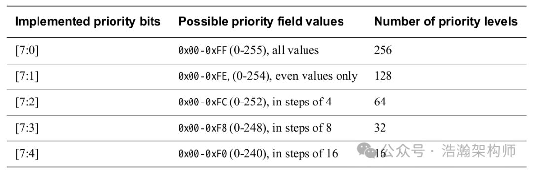
Figure 1-3 GIC Interrupt Levels
The classification in the above diagram is relatively easy to understand; regardless of the configuration, the 8-bit space is what can be used. A brief explanation:
(1) When all 8 bits are utilized, there are a total of 256 levels, with a step size of 1 between adjacent two priority levels.
(2) If configured to only 32 levels, then only the high 5 bits [7:3] of the 8 bits can be used, with a step size of 32 between adjacent two priority levels.
(3) Other configurations can be understood similarly based on (1) and (2).
1.2.3 Highest/Lowest Priority
With so many levels defined, how are high and low priorities determined? Let’s first look at the manual’s introduction:
In the GIC prioritization scheme, lower numbers have higher priority. This means that the lower the assigned priority value, the higher the priority of the interrupt. Priority field value 0 always indicates the highest possible interrupt priority, and the lowest priority value depends on the number of implemented priority levels.
In ARM’s design, the smaller the priority value, the higher the priority; that is, a priority of 0 is the highest, while 255, 254, 252, 248, and 240 are the lowest. To reinforce this understanding, here is a diagram, as shown in Figure 1-4:

Figure 1-4 Highest and Lowest Priorities of GIC Interrupts
1.2.4 Saving Priorities
After clarifying the basic concepts of GIC priorities, we must consider how to save these priorities. Under the GIC architecture, there are four types of interrupts: SPI, SGI, PPI, and LPI. The saving locations differ for each type (the LPI type is not discussed here; other types may vary slightly due to implementation and GIC versions, please note):
SPI
The GICD_IPRIORITYR<n> registers hold the priority value for each supported SPI. An implementation might reserve an SPI for a particular purpose and assign a fixed priority to that interrupt, meaning the priority value for that interrupt is read-only. For other SPIs, the GICD_IPRIORITYR<n> registers can be written by software to set the interrupt priorities. It is IMPLEMENTATION DEFINED whether a write to GICD_IPRIORITYR<n> changes the priority of any active SPI.
SPI type interrupts are saved through the GICD_IPRIORITYR register, as shown in Figure 1-5:

Figure 1-5 GICD_IPRIORITYR<n>
One GICD_IPRIORITYR<n> can describe the priority of four SPI type interrupts. The latest version of the GIC architecture also supports more SPI interrupt priority settings by adding registers GICD_IPRIORITYR<n>.
SGI/PPI
Let’s see where the priorities of SGI and PPI type interrupts are saved?
In a multiprocessor implementation, the GICR_IPRIORITYR<n> and GICR_IPRIORITYR<n>E registers define the interrupt priority of each SGI and PPI INTID independently for each target PE.
SPI type interrupts are saved through the GICR_IPRIORITYR register, as shown in Figure 1-6:

Figure 1-6 GICR_IPRIORITYR<n>
Similarly, one register can save the priority of four interrupt sources; we will not delve further into this.
1.2.5 Group Priority
In the ARM architecture, all interrupt sources are divided into three groups, and the GIC distinguishes the priority of these three groups as it relates to the security state of the PE:
Priority grouping uses the following Binary Point Registers:
• ICC_BPR0_EL1 for Group 0 interrupts. This register is available in all GIC implementations.
• A Non-secure copy of ICC_BPR1_EL1 for Non-secure Group 1 interrupts. If an implementation supports two Security states, there is a Secure and a Non-secure copy of this register. If an implementation supports only one Security state, there is only one copy of this register.
• A Secure copy of ICC_BPR1_EL1 for Secure Group 1 interrupts. This register is available only in a GIC implementation that supports two Security states.
The Binary Point Registers split a priority value into two fields, the group priority and the subpriority. When determining preemption, all interrupts with the same group priority are considered to have the same priority, regardless of the subpriority.
Where multiple pending interrupts have the same group priority, the GIC uses the subpriority field to resolve the priority within a group. Where two or more pending interrupts in a group have the same subpriority, how the GIC selects between the interrupts is implementation specific.
Let’s summarize:
(1) Each interrupt group in ARM has its own priority, which essentially subdivides the original priority, splitting the original 8-bit priority into two parts (Group priority / Subpriority) and assigning different meanings. For example, Group 0 utilizes the register (ICC_BPR0_EL1, Interrupt Controller Binary Point Register 0) to implement the 8-bit priority division, as shown in Figure 1-7:

Figure 1-7 ICC_BPR0_EL1
The Group priority and Subpriority after Binary Point segmentation are shown in Figure 1-8:
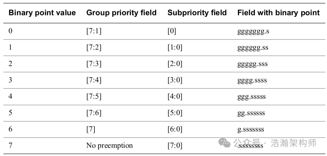
Figure 1-8 GIC-Group-0 Interrupt Group Priority / Subpriority
Other groups have similar mechanisms; we will not elaborate further, but interested readers can refer to the manual.
(2) After the priority permissions are segmented, the GIC-CPU-IF can significantly improve efficiency when determining permissions. It first filters the group of interrupts with lower priority permissions and then compares the Subpriority within the group. The manual provides an example, as shown in Figure 1-9:
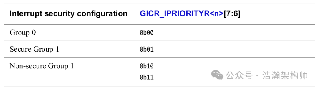
Figure 1-9 Example Priority Allocation
After the priority allocation strategy depicted in the figure above is configured, the following effects can be achieved:
• Some Group 0 interrupts have higher priority than any other interrupts.
• Some Secure Group 1 interrupts have higher priority than any Non-secure Group 1 interrupt.
With the group priority allocation strategy in place, the GIC can flexibly control the selection of the highest priority interrupt in specific scenarios, which we will not expand upon here.
1.2.5 Priority Masking
The GIC’s GIC-CPU-Interfaces can dynamically update ICC_PMR_EL1 at runtime to mask some low-priority interrupts, as explained below:
The Priority Mask Register for a CPU interface, ICC_PMR_EL1, defines a priority threshold for the target PE. The highest pending interrupt is masked by ICC_PMR_EL1 when either of the following is true:
• The interrupt is not an NMI and the interrupt priority is equal to or lower than ICC_PMR_EL1.Priority.
• GICD_CTLR.DS is 0 and either of the following is true:
— The interrupt is a Non-secure NMI and ICC_PMR_EL1.Priority is set to a priority in the Secure range.
— The interrupt is a Non-secure NMI, the current Security state is Secure or Root, and ICC_PMR_EL1.Priority is set to the highest implemented Non-secure priority.
The GIC only signals pending interrupts that have a higher priority than this priority threshold to the target PE. A value of zero, the register reset value, masks all interrupts from being signaled to the associated PE. The GIC does not use priority grouping when comparing the priority of a pending interrupt with the priority threshold.
Let’s take a look at the manual’s description of the structure of ICC_PMR_EL1, as shown in Figure 1-10:

Figure 1-10 GIC ICC_PMR_EL1
Let’s see how ICC_PMR_EL1 implements priority masking to filter interrupts (this part will not be expanded upon; just understanding the basic principle is sufficient):
Provides an interrupt priority filter. Only interrupts with a higher priority than the value in this register are signaled to the PE.
Writes to this register must be high performance and must ensure that no interrupt of lower priority than the written value occurs after the write, without requiring an ISB or an exception boundary.
1.2.6 Non-Maskable Interrupt (NMI) Prioritization
The higher version of GIC introduces the non-maskable property for SPIs, PPIs, and SGIs. Support for GICv3.3 is indicated by GICD_TYPER2.NMI.
When GICD_CTLR.DS = 0, NMIs have the following priorities:
• Secure NMIs have a higher priority than a non-NMI with priority 0x00.
• Non-secure NMIs have the following priority:
— Higher priority than a non-NMI with priority 0x80.
— Lower priority than a non-NMI with priority 0x7F.
When GICD_CTLR.DS == 1, NMIs have a higher priority than a non-NMI with priority 0x00.
With the introduction of NMI type priorities, the world of GIC interrupt priorities has changed, as shown in Figure 1-11:
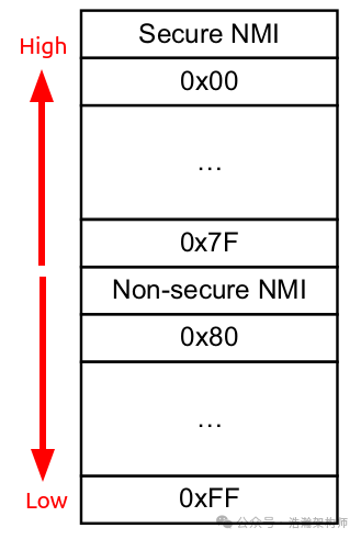
Understanding Figure 1-11 should make the content of section 1.2.5 clearer; we will not elaborate further. Essentially, on the basis of the original interrupt priority levels, two NMI type priorities have been added, while the original priority range has been divided into two segments: one for secure state priority and the other for Non-Secure priority.
1.2.6 Interrupt Priority and Security State
In the previous sections, you should have noticed that the PE’s security state is coupled with priority. In reality, the situation is deeply coupled, and depending on various configurations and implementation schemes, there are many rules. Here, we will only provide a simple summary; detailed information requires you to read the manual for specifics.
1.2.6.1 Non-secure Access to Secure Interrupt Priorities
The manual describes it as follows:
To support the Armv8 Security model, the register fields associated with Secure interrupts are RAZ/WI for Non-secure accesses.
In summary, when the PE is in Non-Secure state, reading the priority registers of Group-0 and Secure-Group-1 interrupts will always return a priority of 0x00, which is the highest priority. Write actions to these registers will be ignored.
For example, if an SPI interrupt is configured in GICD_IPRIORITYR<n> with a permission of 0x01, and the GIC initializes this SPI interrupt as part of Secure-Group0 or Secure Group1 through the initialization register GICD_IGRPMODR, when the PE operates in Non-Secure state and accesses the priority register of this SPI interrupt, it will always return 0x00 upon reading, and writing will be directly ignored.
1.2.6.2 Accessing Non-secure Group 1
Let’s first review the manual’s introduction (a warning: if you are interested in this scenario, it is strongly recommended to read the manual):
• When a PE reads the priority value of a Non-secure Group 1 interrupt, the GIC returns either the Secure or the Non-secure read of that value, depending on whether the access is Secure or Non-secure.
• This model for the presentation of priority values ensures that software written to operate with an implementation of this GIC architecture functions as intended regardless of whether the GIC provides support for two Security states. However, programmers must ensure that software assigns the appropriate priority levels to the Group 0 and Group 1 interrupts.
• This ensures that all Group 0 and, if applicable, Secure Group 1 interrupts have higher priorities than all Non-secure Group 1 interrupts. However, a system might have requirements that cannot be met with this scheme.
Combining the manual’s description, the author believes that ARM’s design mechanism has two purposes:
• Regardless of whether ARM supports Security states, ensure that software sees consistent access (read/write) to interrupt priority-related areas.
• Under any circumstances, regardless of how the PE accesses (read/write), it ensures that the priority of interrupts belonging to the secure group is higher than that of non-secure interrupts.
Let’s discuss briefly:
(1) ARM divides interrupt priorities (0x00 to 0xFF) into two parts, with the higher priority area assigned to (Secure Group-0, Secure Group-1), while the lower priority part is assigned to Non-Security-1, as shown in Figure 1-12:
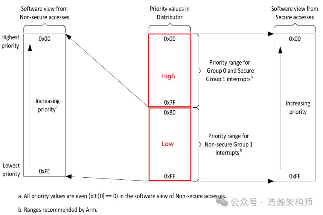
Figure 1-12 Software Reads of the Priorities of Group 1 and Group 0 Interrupts
When the PE is in Security state, reading the interrupt priority returns the actual value from the corresponding register. When the PE is in Non-Secure state, the situation is more complex. Referring to Figure 1-13, the following effects can be achieved:
• Reading the priority of Group 0 and Secure Group 1 interrupt signals will directly return 0x00 (highest priority), as introduced in the previous section.
• Reading the priority of Non-Secure Group 1 interrupt signals, the GIC will left-shift the priority value by one position, filling the lower bit with 0.
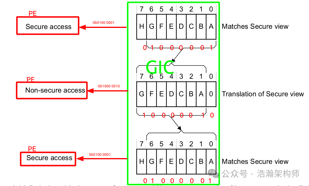
Figure 1-13 Relationship between Secure and Non-secure Reads of Interrupt Priority Fields
Note that although left-shifting is performed, Non-Secure Group 1 will still not exceed the priority of Secure interrupts.
The above only illustrates the reading scenario; similar processing mechanisms also apply when writing to GIC subsystems to ensure the priority of secure interrupts. Due to space limitations, we will not expand on this.
1.2.6.3 Security State and GIC
Through the access to priority-related registers, we can see that the effects of accessing GIC-related registers vary depending on the PE’s state. There are many unspoken rules, and we cannot summarize them exhaustively here. We can only borrow a description from the manual to help establish a general rule in your mind:
The key characteristics of the scheme are:
• Some registers, such as the Distributor Control Register, GICD_CTLR, and the Redistributor Control Register, GICR_CTLR, are banked by security, providing separate Secure and Non-secure copies of the registers. A Secure access to the address accesses the Secure copy of the register. A Non-secure access to the address accesses the Non-secure copy.
• Some registers, such as the Interrupt Group Registers, GICD_IGROUPRn, are only accessible using Secure accesses.
• Non-secure accesses to registers, or parts of a register, which are only accessible to Secure accesses are Read-As-Zero and Writes Ignored (RAZ/WI).
1.2.7 Priority Handling Scenarios
Let’s do a quick review. When we introduced the GIC’s interrupt state machine and lifecycle, we mentioned that pending interrupts must undergo a series of checks before being acknowledged by the PE-Core, with the final check being priority verification and arbitration:
(1) Check the interrupt priority and priority mask to decide which PEs are suitable to handle the interrupt.
• Each PE has a Priority Mask register, ICC_PMR_EL1, in its CPU interface. This register sets the minimum priority required for an interrupt to be forwarded to that PE. Only interrupts with a higher priority than the mask are signaled to the PE.
(2) Check the running priority to decide which PEs are available to handle the interrupt.
• Running priority and preemption cover running priority and how this affects preemption. If the PE is not already handling an interrupt, the running priority is the idle priority: 0xFF. Only an interrupt with a higher priority than the running priority can preempt the current interrupt.
(3) A CPU interface provides an interface to a PE that is connected to the GIC. Each CPU interface is connected to a single PE.
A CPU interface receives pending interrupts prioritized by the IRI and determines whether the interrupt is a member of a group that is enabled in the CPU interface and has sufficient priority to be signaled to the PE. At any time, the connected PE can determine the:
• INTID of its highest priority pending interrupt, by reading ICC_HPPIR0_EL1 or ICC_HPPIR1_EL1.
• The running priority of the CPU interface by reading ICC_RPR_EL1.
(5) If, on a particular CPU interface, multiple pending interrupts have the same priority and have sufficient priority for the interface to signal them to the PE, it is IMPLEMENTATION DEFINED how the interface selects which interrupt to signal.
• GICv3 guarantees that the highest priority, unmasked, enabled interrupt will be delivered to a target PE in finite time.
• There is no guarantee that higher priority interrupts will always be taken before lower priority interrupts, although this will generally be the case.
(6) When the PE acknowledges an SGI, a PPI, or an SPI at the CPU interface, the CPU interface can signal another interrupt to the PE to preempt interrupts that are active on the PE. If there is no pending interrupt with sufficient priority to be signaled to the PE, the interface deasserts the interrupt request signal to the PE.
We have summarized the core ideas of interrupt handling contexts above. Here, we summarize the principles related to priorities in GIC interrupt handling:
(1) First, it is important to clarify that among the three core components of GIC (Distributor, Redistributor, CPU-Interfaces), the GIC-CPU-IF is the main force in handling interrupt priorities. The main focus of GIC-CPU-IF in managing interrupt priorities is through several internal system registers, as shown in Figure 1-14 (Note: the system registers inside are highly dependent on the chip manufacturer’s implementation of GIC; this is just a schematic):
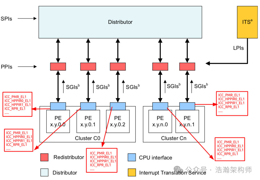
Figure 1-14 System Registers Related to GIC-CPU-Interfaces
(2) With the registers in GIC-CPU-IF, the GIC must initialize and maintain these registers during both the initialization phase and runtime. When interrupt signals arrive, the GIC filters interrupt signals based on the priorities stored in these registers. The general processing steps are as follows:
• Filter out the highest priority pending interrupt using system registers ICC_HPPIR0_EL1 or ICC_HPPIR1_EL1.
• Use ICC_PMR_EL1 to filter out interrupt signals that the current CPU-IF does not need to respond to.
• For interrupt signals that pass the mask check, if the current PE is not in interrupt handling state, it will be directly acknowledged by the PE.
• For interrupt signals that pass the mask check, if the current PE is in interrupt handling state, further filtering by the ICC_RPR_EL1 register will occur; if it passes, the current interrupt signal will preempt the previous interrupt handling state.
(3) Two concepts are crucial in the above processing steps, and we need to pay attention to them:
Running priority
At any given time, the running priority of a CPU interface is either:
• The group priority of the active interrupt for which there has not been a priority drop on that interface.
• If there is no active interrupt for which there has not been a priority drop on the interface, the running priority is the idle priority: 0xFF.
Sufficient priority
The GIC CPU interface compares the priority of an enabled, pending interrupt with all of the following to determine whether the interrupt has sufficient priority:
• The Priority Mask Register, ICC_PMR_EL1.
• The preemption settings for the interface, as indicated by ICC_BPR0_EL1 and ICC_BPR1_EL1.
• The current running priority, as indicated by ICC_RPR_EL1 for the CPU interface. If the interrupt has sufficient priority, it is signaled to the connected PE.
Interrupt signals that can be acknowledged by the PE (normal acknowledgment/preemptive acknowledgment) must have sufficient priority after passing various filters.
1.3 Interrupt Preemption and Nesting
In the previous section, we mentioned the concept of interrupt preemption when discussing GIC priorities; that is, while the PE is responding to one interrupt, it can still respond to other more urgent interrupts. This section will share this from two perspectives: the GIC interrupt preemption mechanism and the ARM Exception mechanism.
1.3.1 Interrupt Preemption
Let’s first look at the manual’s description of GIC preemption:
Preemption
A CPU interface supports signaling of higher priority pending interrupts to a target PE before an active interrupt completes. A pending interrupt is only signaled if one of the following is true:
• When a PE acknowledges an interrupt, its running priority becomes the same as the priority of the interrupt.
• The highest priority pending interrupt is not an NMI, and both of the following are true:
— Its priority is higher than the priority mask for that CPU interface.
— Its group priority is higher than that of the running priority on the CPU interface.
• The highest priority pending interrupt is an NMI, and one of the following is true:
— The group priority of the higher priority pending interrupt is higher than the running priority.
— The group priority of the higher priority pending interrupt is equal to the running priority, and ICC_AP1R0_EL1.NMI is 0 for the Security state owning the interrupt.
Combining the manual’s description, we can analyze the following:
(1) Preemption occurs when the current PE is processing an interrupt signal.
(2) The current PE’s Running priority and the priority of the interrupt being processed are the same, meaning this priority is a dynamic value maintained by the GIC in an internal register (ICC_RPR_EL1, Interrupt Controller Running Priority Register), as shown in Figure 1-15.

Figure 1-15 GIC-CPU-Interface-ICC_RPR_EL1
(3) An example of the current GIC-CPU-Interface’s Running Priority change process during operation is shown in Figure 1-16.
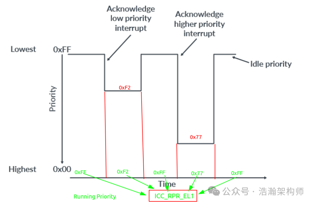
Figure 1-16 GIC-CPU-Interface-ICC_RPR_EL1
(4) When GIC does not support preemption, the interrupt processing timing is illustrated in Figure 1-17:
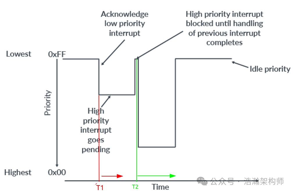
Figure 1-17 GIC Without Preemption
When a low-priority interrupt is acknowledged by the PE at time T1, if the current GIC configuration does not support preemption, any higher-priority interrupt arriving after time T1 will remain in Pending status until the low-priority interrupt is processed by the PE at time T2.
(5) When GIC supports preemption, the interrupt processing timing is illustrated in Figure 1-18:
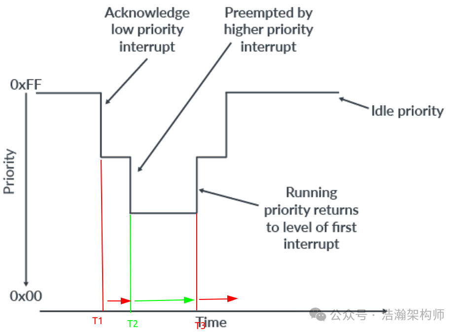
Figure 1-18 GIC With Preemption
When GIC is configured to support interrupts, if a low-priority interrupt is acknowledged by the PE at time T1, and during the processing of this low-priority interrupt, a high-priority interrupt becomes pending at time T2, the PE will be preempted by the current high-priority interrupt and will process it until time T3, at which point the PE will return to the previously preempted low-priority interrupt signal.
1.3.3 Interrupt Nesting
For the ARM architecture, interrupts are a subset of the ARM exception system, and exception handling is inseparable from the upper-level RichOS. In this section, we will look at interrupt preemption from the perspective of exception handling.
1.3.3.1 Context Switching
From the previous discussion, interrupt preemption seems simple. However, it is not because it involves an important concept: CPU context. A CPU’s PE can only have two contexts during operation: interrupt context and process context. Modern processors must match modern operating systems to function effectively, and modern operating systems are primarily multitasking, meaning they share PE resources over time. This sharing process is also a context-switching process, as introduced in the manual:
Exactly what has to be saved and restored varies between different operating systems, but typically a process context switch includes saving or restoring some or all of the following elements:
• general-purpose registers X0-X30.
• Advanced SIMD and Floating-point registers V0 – V31.
• Some status registers.
• TTBR0_EL1 and TTBR0.
• Thread Process ID (TPIDxxx) Registers.
• Address Space ID (ASID)
This switching process requires saving and restoring contexts, including but not limited to the above elements. More importantly, this process consumes PE resources, and if it occurs too frequently, it can affect the current CPU performance (it’s strange that many kernel maintainers and developers engaged in virtualization work do not understand this).
1.3.3.2 Interrupt Nesting
Let’s examine the model of exception handling when GIC supports preemption, as shown in Figure 1-19:
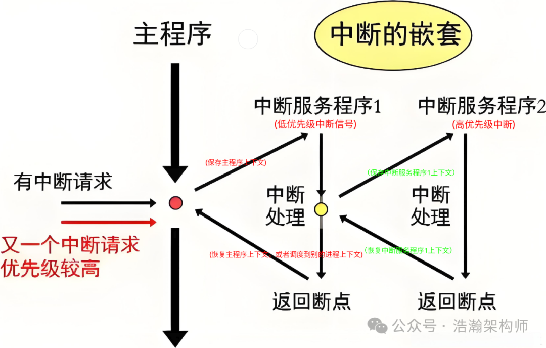
Figure 1-19 GIC Interrupt Preemption Exception Handling Model
According to ARM’s exception handling mechanism, if the GIC’s interrupt preemption function is enabled, then nested interrupts must be implemented internally in the PE with the cooperation of the operating system. We will briefly analyze this:
(1) This process is a long link, pulling the handling of the interrupt upper half from microsecond-level to millisecond-level, which poses a challenge to the real-time nature of interrupt signals. This is unfair to the nested low-priority interrupt signals; for example, Linux does not discriminate against low-priority processes and has implemented the CFS fair scheduling mechanism.
(2) Interrupt nesting also increases the complexity of operating system design. The more complex the system, the more prone it is to errors, and the maintenance costs are also very high. Therefore, various operating systems are cautious about supporting this feature of interrupt nesting. The default configuration of Linux does not support interrupt nesting, and enabling it requires extensive customization and validation work.
Conclusion
This article introduced the concept of interrupt priority and enriched the details of the GIC interrupt handling process. It also discussed scenarios related to interrupt priority handling concerning interrupt preemption and briefly introduced the concept of interrupt nesting. Priority itself is not complicated, but when combined with the execution permissions and execution states of the processor, it becomes complex. This article only provided a high-level overview of the main knowledge regarding GIC priorities, and for those interested in the details, further reading of the manual is recommended.
We are now in the era of large models, and everyone should have a sense of urgency. When utilizing large models, consider that in the future, your competition may not be another human but a machine. Value this matter but do not be anxious; I believe the world remains material, and regardless of the situation, machine knowledge comes from human exploration and creation. In the future, everyone may have their own exclusive large model, like an electronic pet, but this pet will possess richer knowledge, and the upper limit of its abilities may be the upper limit of its owner’s abilities. Therefore, everyone should actively learn to cope with this ever-changing and fascinating world.
Reference
[00] <Armv8-A-virtualization.pdf>
[01] <DEN0024A_v8_architecture_PG.pdf>
[02] <learn_the_architecture_aarch64_exception_model.pdf>
[03] <corelink_gic_720ae_generic_interrupt_controller_trm.pdf>
[04] <arm_generic_interrupt_controller_v3_and_v4_virtualization_guide.pdf>
[05] <learn_the_architecture_generic_interrupt_controller_v3_and_v4_lpis.pdf>
[06] <80-ARM-GIC-wx0005_Arm-gicv3_v4学习这一篇就够了.pdf>
[07] <80-ARM-GIC-wx0003_ARM架构Generic-Interrupt-Controller-GIC之Distributor和CPU-interface.pdf>
[08] <80-ARM-GIC-HK0001-一文搞懂GICv3中断控制器的工作原理.pdf>
[09] <80-ARM-GIC-wx0001_ARM-gicv3_gicv4的总结-基础篇.pdf>
[10] <80-ARM-INT-yk0001_万字长文玩转中断:从硬件看中断之GIC.pdf>
[11] <learn_the_architecture_generic_timer.pdf>
[12] <learn_the_architecture_trustzone_for_aarch64.pdf>
[13] <learn_the_architecture_realm_management_extension.pdf>
Glossary
GIC – Generic Interrupt Controller
SCMI – System Control and Management Interface (SCMI)
ACPI – Advanced Configuration and Power Interface (ACPI)
PSCI – Power State Coordination Interface (PSCI)
UEFI – Unified Extensible Firmware Interface (UEFI)
UART – Universal Asynchronous Receiver/Transmitter
SPI – Shared Peripheral Interrupt
PPI – Private Peripheral Interrupt
SGI – Software Generated Interrupts
MPAM – Memory System Resource Partitioning and Monitoring
LPI – Locality-specific Peripheral Interrupt (LPI)
PE – Processing Element
MSI – message-signaled interrupts (MSI)
IAR – Interrupt Acknowledge Registers
EOIR – End of Interrupt Registers
IRM – Interrupt Routing Mode
ITS – Interrupt Translation Service
ITT – Interrupt Translation Tables
vPE -virtual processing element
IPI – inter-processor interrupts
IRI – Interrupt Routing Infrastructure
EOI – End of interrupt
REE – Rich Execution Environment
TEE – Trusted Execution Environment
NMI – Non – Maskable Interrupts
RAZ – Read-As-Zero
WI – Writes Ignored