Click the blue "Arm Selected" in the upper left corner and select "Set as Favorite"Thoughts 1. Why use virtual addresses? Why use MMU? 2. The MMU hardware completes address translation, what else do we need to do in software? 3. Where is the MMU? What is the relationship between MMU and SMMU?
1. Introduction to MMU Concept
The MMU consists of two parts: TLB maintenance and address translation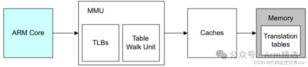
The main function of the MMU is address translation, which converts virtual addresses to physical addresses, whether they are main memory addresses (DDR addresses) or IO addresses (device addresses). In systems with MMU enabled, the instructions executed by the CPU read and write data using virtual addresses. Inside the ARM core, virtual addresses are automatically converted into corresponding physical addresses by the MMU, which are then sent to the AXI bus to complete read and write access to real physical memory and physical devices.
So why use an MMU? Why use virtual addresses? Here are three points summarized:
1. Multiple programs can execute independently — no need to know the specific physical addresses.
2. Virtual addresses are contiguous — allowing programs to run across multiple segments of physical memory.
3. Allows the operating system to manage memory — including determining the visible memory range, permissions for reading and writing, and cache attributes.
When the MMU is enabled, the hardware automatically converts virtual addresses to physical addresses, so what does the software need to do? That is, what steps are required to create a page table translation? In other words, what tasks must the software perform to enable an MMU?
-
Set the page table base address TTBR (specify the location of the translation table).
-
Initialize MAIR_EL3 (Memory Attribute Indirection Register).
-
Configure TCR_EL3 (configure the translation mechanism).
-
Create a page table (generate the translation table).
-
Enable the MMU.
2. Range of Virtual Address Space and Physical Address Space
2.1. (Virtual/Physical) Address Space Range
In previous operating system studies, we often hear a saying: the kernel’s virtual address space range is 3G-4G, while the application’s virtual address space range is 0-3G; but on aarch64, it is: the kernel’s virtual address space is 0xffff_0000_0000_0000 – 0xffff_ffff_ffff_ffff, while the application’s virtual address space is: 0x0000_0000_0000_0000 – 0x0000_ffff_ffff_ffff.
However, it must be pointed out that the above statements contain two errors:
1. ARM processors do not specify which address space the kernel must use. The above example is a design choice of the Linux kernel, which uses the address range 0xffff_0000_0000_0000 – 0xffff_ffff_ffff_ffff for the Linux kernel, while the user space uses the address range 0x0000_0000_0000_0000 – 0x0000_ffff_ffff_ffff. Here, we can give a counterexample, such as Optee OS, which uses high virtual address space for both kernel mode and user mode.
2. The number of high bits is not fixed, but is determined by the effective virtual address bits used by the operating system. For example, in Optee, both kernel mode and user mode have a virtual address space range of: 0x0000_0000_0000_0000 – 0x0000_0000_ffff_ffff.
In fact, there is a standard description in the ARM documentation:
-
If the high bit of the virtual address is 1, then the translation will use the TTBR1_ELx base address register; if the high bit of the virtual address is 0, then the translation will use the TTBR0_ELx base address register. Therefore, it cannot be said that which register (TTBR0/TTBR1) is used and then determines which virtual address space is used; rather, it should be said that the operating system (or user space software) uses which set of virtual address space, thus determining which base address register (TTBR0/TTBR1) is used for translation.
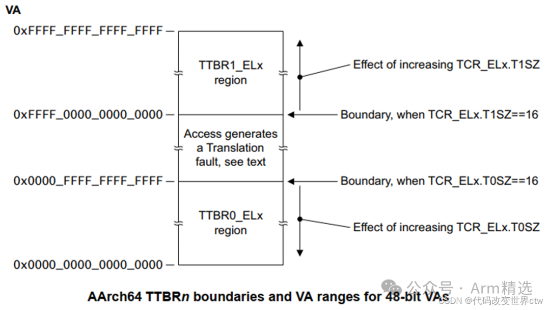 The following is an excerpt from the official description of the ARM documentation:
As Figure shows, for 48-bit VAs:• The address range translated using TTBR0_ELx is 0x0000000000000000 to 0x0000FFFFFFFFFFFF.• The address range translated using TTBR1_ELx is 0xFFFF000000000000 to 0xFFFFFFFFFFFFFFFF.In an implementation that includes ARMv8.2-LVA and is using Secure EL3 the 64KB translation granule, for 52-bit VAs:• The address range translated using TTBR0_ELx is 0x0000000000000000 to 0x000FFFFFFFFFFFFF.• The address range translated using TTBR1_ELx is 0xFFF0000000000000 to 0xFFFFFFFFFFFFFFFF.Which TTBR_ELx is used depends only on the VA presented for translation. The most significant bits of the VA must all be the same value and:• If the most significant bits of the VA are zero, then TTBR0_ELx is used.• If the most significant bits of the VA are one, then TTBR1_ELx is used.
2.2. Effective Bits of Physical Address Space (Range)
The number of physical address bits for each core is fixed, while the number of virtual address bits can be configured according to the needs of compilation or development. Below is an excerpt of the effective number of physical address bits for some ARM cores:
2.2.1. Configuration of Page Table Translation Related Registers
-
ID_AA64MMFR0_EL1.PARange: Physical address size : Read the ARM register to obtain how many bits of effective physical address the current system supports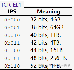
-
TCR_EL1.IPS: Output address size : Tells MMU how many bits of physical address you need
-
TCR_EL1.T0SZandTCR_EL1.T1SZ: Input address size : Tells MMU how many effective bits of virtual address I input
3. Translation Regimes
The Memory Management Unit (MMU) performs address translation, which includes the following components:
1. Table Walk Unit: Responsible for reading the page table from memory and completing address translation.
2. Translation Lookaside Buffers (TLBs): This is a cache, similar to cache, used to store recent address translation results.
When software sends a memory address to the MMU, these addresses are all virtual addresses. The MMU checks if there are any recently cached address translation results in the TLB. If the recent cached translation result is not found in the TLB, the translation unit will read the appropriate one or more table entries from memory for address translation, as shown in the following steps:
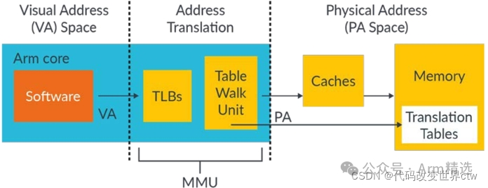
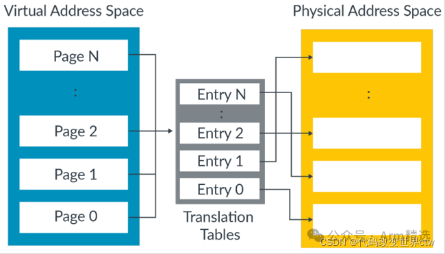
The working principle of Translation tables is to divide the virtual address space into equally sized blocks and provide an entry for each block.
In these translation tables, each entry corresponds to a block in the virtual address space. For example, entry 0 provides the mapping for block 0, entry 1 provides the mapping for block 1, and so on. Each entry contains the address of the corresponding physical memory block and the attributes that should be used when accessing the physical address.
 In the current ARMV8/ARMV9 architecture (excluding the armv9 RME extension), there are at least the following 9 types of Translation regime:
Secure EL1&0 translation regime, when EL2 is disabled Non-secure EL1&0 translation regime, when EL2 is disabled Secure EL1&0 translation regime, when EL2 is enabled Non-secure EL1&0 translation regime, when EL2 is enabled Secure EL2&0 translation regime Non-secure EL2&0 translation regime Secure EL2 translation regime Non-secure EL2 translation regime Secure EL3 translation regime
The address translation scenarios for these 9 types of Translation regime are shown in the following figure: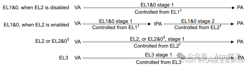
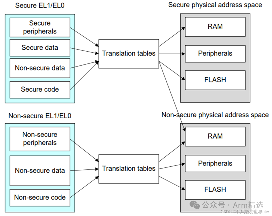
In a dual system environment with REE (Regular Execution Environment running Linux) and TEE (Trusted Execution Environment running Optee), both systems’ Memory Management Units (MMUs) can be enabled simultaneously.
In this dual system environment, there will be two sets of different page tables, used for Secure and Non-secure address spaces respectively. The Secure page table can map Non-secure memory, meaning that the Secure environment can access memory in the Non-secure environment. However, the Non-secure page table cannot map Secure memory, otherwise, an error will occur during address translation.
This setup ensures memory access security between Secure and Non-secure environments, preventing the Non-secure environment from accessing sensitive data in the Secure environment.
 Two Stage Translations The EL1&0 Translation regime is in VM (Virtual Machine) or SP (Secure Partition) when EL2 is enabled, and requires stage 2 translation. For EL2 Translation regime and EL3 Translation regime, stage 2 translation is not used.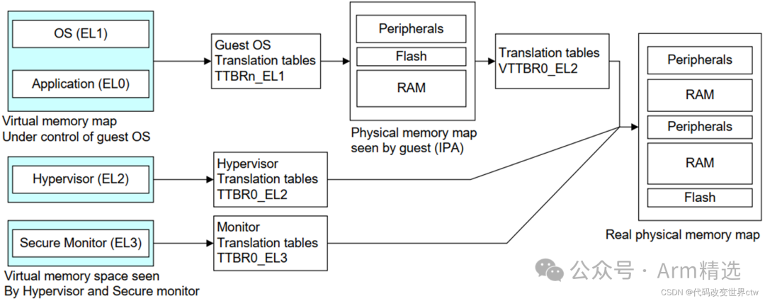
4. Address Translation/How Many Levels of Page Table?
4.1. Thought: How many levels of page tables are there?
From the following figure, some page tables start from L2, some from L1, some from L0, and others from L-1, all terminating at L3. So how many levels of page tables do we actually have?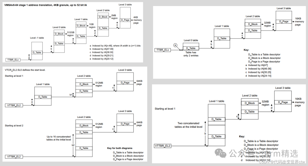
4.2. Taking 4KB granule as an example, the composition method of page tables
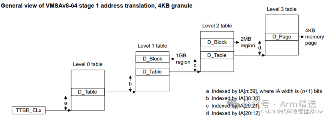
For the case where the effective bits of the virtual address are 48 bits, here are some key points summarized:
-
The first level table (Level 0 table) uses bits [47:39] for indexing, with 512 offsets.
-
The second level table (Level 1 table) uses bits [38:30] for indexing, also with 512 offsets.
-
The third level table (Level 2 table) uses bits [29:21] for indexing, still with 512 offsets.
-
The fourth level table (Level 3 table) uses bits [20:12] for indexing, again with 512 offsets.
It should be noted that in the Level 0 table, it can only point to D_Table and cannot point to D_Block.
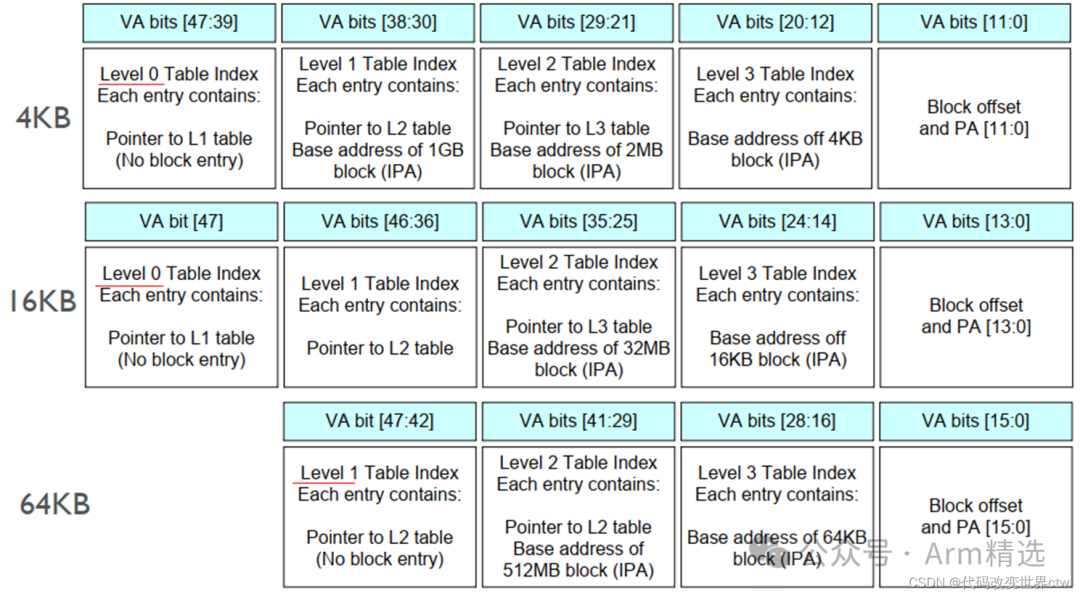
Additionally, it should be emphasized that when the number of virtual address bits exceeds 48 bits, according to ARM regulations, there is only one situation, which is when the number of virtual address bits is 52 bits, and in this case, the minimum granule size is specified as 64KB. In this discussion, we mainly focus on the case where the number of virtual address bits is 48 bits, where the granule size is 4KB.
4.3. Example of Actual Use in Optee
32-bit effective virtual address, 3-level page table query (L1, L2, L3), granule size 4KB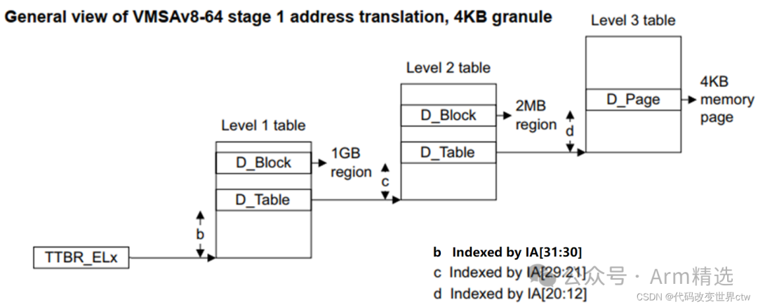
The following shows the page table structure of Optee OS, where TTBR0_EL1 points to the L1 Table, and the L1 Table has 4 entries, but only uses 3, corresponding to 3 L2 Tables.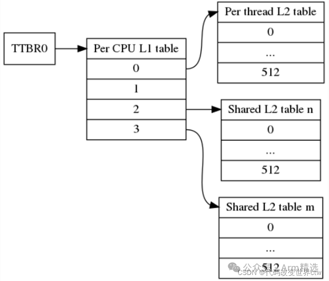 The configuration-related code is as follows: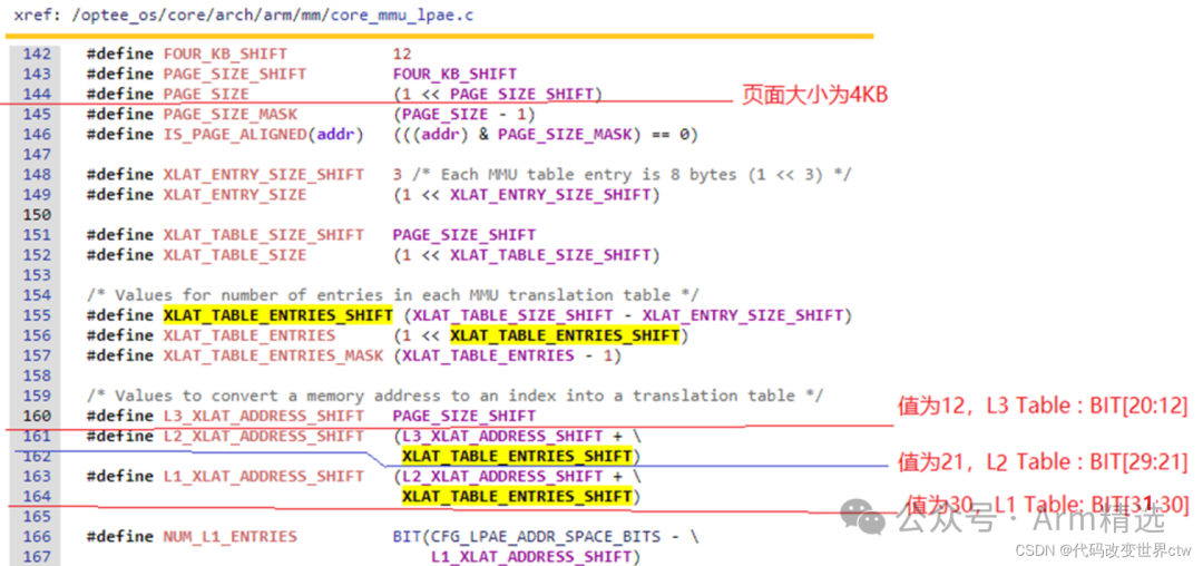
In the ARMv8 architecture, three different page table formats are supported, of which we only study the AArch64 Long Descriptor.
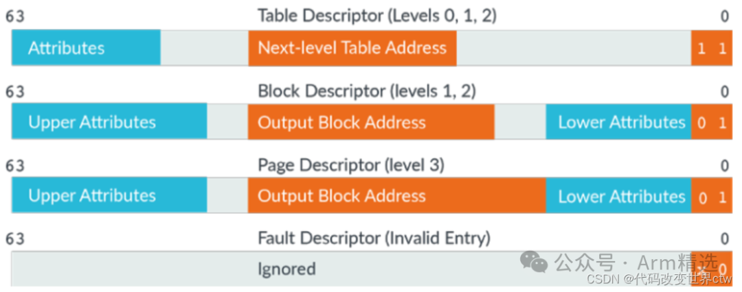
AArch64 Long Descriptor supports four different entry types:
1. Invalid or fault entry: indicates that the entry is invalid or there is a fault.
2. Table entry: points to the entry of the next-level translation table.
3. Block entry: defines the memory attributes when accessing memory.
4. Reserved format: reserved field, currently considered invalid.
It should be noted that entry[1:0] indicates which type this entry belongs to, where Block Descriptor and Page Descriptor have the same meaning. In the current architecture, reserved fields are also considered invalid.
5.3. Introduction to Page Table Attribute Bits (Block Descriptor/Page Descriptor)
5.3.1. Page Table Attributes of Stage 1
(Attribute fields in stage 1 VMSAv8-64 Block and Page descriptors)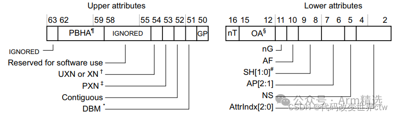
In stage 2 VMSAv8-64, the attribute fields in the page table descriptor are as follows:
-
PBHA, bits [62:59]: used for FEAT_HPDS2.
-
XN or UXN, bit [54]: indicates execution prohibition or non-privileged execution.
-
PXN, bit [53]: indicates privilege execution prohibition.
-
Contiguous, bit [52]: indicates that the translation table entry is contiguous and can exist in one TLB entry.
-
DBM, bit [51]: indicates the dirty bit modifier.
-
GP, bit [50]: used for FEAT_BTI.
-
nT, bit [16]: used for FEAT_BBM.
-
nG, bit [11]: indicates whether the translation table in TLB is cached using ASID.
-
AF, bit [10]: indicates access flag, when AF=0, it will be set to 1 during the first access to this page, indicating it has been accessed for the first time.
-
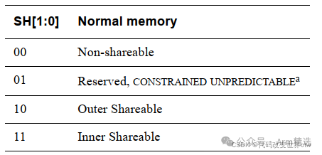
SH, bits [9:8]: shared attributes.
-
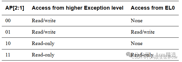
AP[2:1], bits [7:6]: data access permission bits.
-
NS, bit [5]: non-secure bit.
-
AttrIndx[2:0], bits [4:2]: attribute index.
These attribute fields are used to describe the block (Block) and page (Page) descriptors in the page table, controlling the behavior and characteristics of memory access.
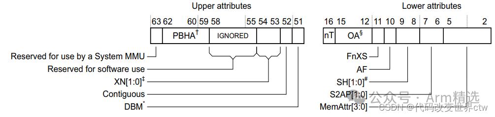
In the page table descriptor of VMSAv8-64, here are detailed introductions to other flag bits:
-
PBHA[3:1], bits[62:60]: reserved fields for FEAT_HPDS2.
-
PBHA[0], bit[59]: reserved field for FEAT_HPDS2.
-
XN[1:0], bits[54:53]: Execute-never settings.
-
Contiguous, bit[52]: indicates whether the translation table entry is contiguous and can exist in one TLB Entry.
-
DBM, bit[51]: dirty bit modifier.
-
nT, bit[16]: used for FEAT_BBM.
-
FnXS, bit[11]: used for FEAT_XS.
-
AF, bit[10]: access flag.
-
SH, bits[9:8]: shared attributes.
-
S2AP, bits[7:6]: Stage 2 data access permissions.
-
MemAttr, bits[5:2]: memory attributes, pointing to the attrn attribute field in MAIR_ELx register, indicating the cache attributes of memory, such as cacheable, shareable, etc.
-
NS, bit[1]: non-secure bit, indicating whether the converted physical address is secure or non-secure.
-
AP, bits[0]: data access permission, used to control access permissions to data.
-
(4) SH
-
shareable attribute
(5) AF (Access Flag):
The AF flag is used to indicate the access status of the page. When the AF bit is 0, it indicates that the page has not been accessed yet. When the page is accessed for the first time, the system sets the AF bit to 1, indicating that the page has been accessed for the first time.
(6) nG:
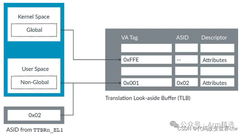
In the EL0/EL1 virtual address space, the nG bit in the attribute field of the page descriptor marks the translation as Global (G) or Non-Global (nG). Global translations apply to any application currently running, while Non-Global translations apply only to specific applications.
Non-Global mappings are tagged in the TLB using ASID. During TLB lookups, the ASID in the TLB entry is compared with the currently selected ASID. If they do not match, the TLB entry is not used.
The following figure shows the case where there is no ASID tag for global mapping in kernel space and where there is an ASID tag for non-global mapping in user space.
(7) XN or UXN privilege and non-privilege flags indicating that instructions cannot be executed from this memory region: Execute-never Unprivileged execute-never
6. Introduction to Address Translation Instructions
There are about 14 instructions for address translation: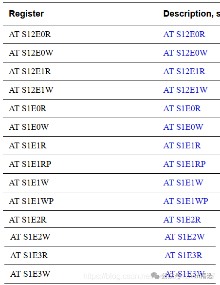 To summarize: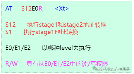
7. Summary of System Registers Related to Address Translation
Address translation is controlled by a combination of system registers:
7.1 SCTLR_ELx

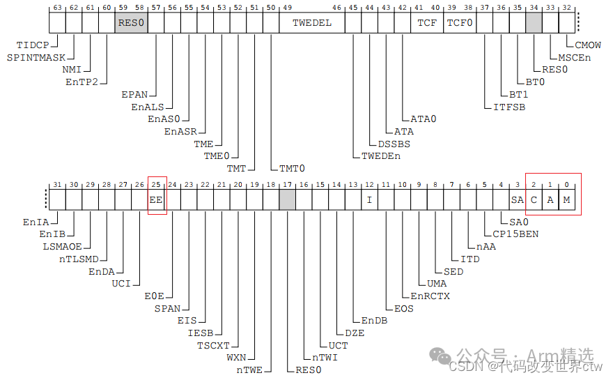
The system control register controls the opening and closing of the MMU, I-cache, D-cache, and also controls the endianness of translation table walks accessing memory.
-
M – Enable Memory Management Unit (MMU).
-
C – Enable for data and unified caches.
-
EE – Endianness of translation table walks.
7.2 TTBRn_ELx
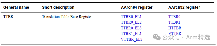

-
BADDR : Base address
-
ASID : Distinguish TLB entry for user programs using ASID
7.3 TCR_ELx
In the ARM Core (aarch64), there are three Translation Control Registers:
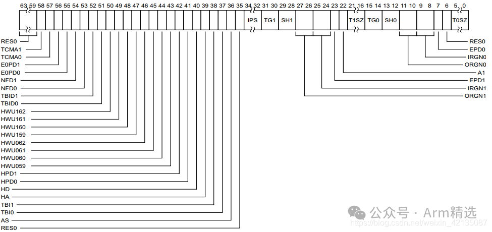
| Bit Position | Function | Description |
|---|---|---|
| ORGN1、IRGN1、ORGN0、IRGN0 | cacheable attributes | outer/inner cableability attributes (such as write-through mode, write-back mode) |
| SH1、SH0 | shareable attributes | cache sharing attribute configuration (such as non-shareable, outer/inner shareable) |
| TG0/TG1 | Granule size | Granule size (actually the page size, 4k/16k/64k) |
| IPS | Physical address size | Physical address size, such as 32bit/36bit/40bit |
| EPD1、EPD0 | – | Enable and disable TTBR_EL1/TTBR_EL0 |
| TBI1、TBI0 | – | top addr is ignore, or used for MTE calculation |
| A1 | – | Selection of ASID, whether to use that in TTBR_EL1 or TTBR_EL0 |
| AS | – | Whether ASID is 8bit or 16bit |
7.3 MAIR_ELx
Memory Attribute Register, divided into 8 Attrn, so each core supports at most 8 memory attributes. Each entry in the page table will point to an Attr field.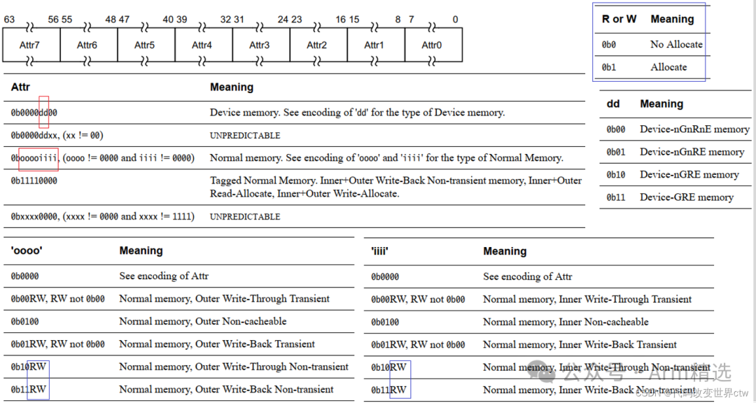
Latest Courses☞【Course】8 Days to Learn ARM Architecture☞【Course】“8 Days to Learn Trustzone/TEE/Security Architecture” Limited Time 128 YuanClassic Course☞【Member】Arm Selected Classroom – Platinum VIP Introduction  ☞【Course】”From Beginner to Expert in ARMv8/ARMv9 Architecture” – Phase II Video Course ☞【Course】Trustzone/TEE/Security from Beginner to Expert – Standard Version Video Course ☞【Course】Secureboot from Beginner to Expert (Phase II) ☞【Course】CA/TA Development from Beginner to Expert☞【Course】”ATF Architecture Development Detailed Explanation” – Video Course☞【Course】”Optee System Development Detailed Explanation” – Video Course☞【Course】ATF/optee/hafnium/linux/xen Code Reading☞【Course】HSM/HSE/SHE/SE/Crypto engine Introduction☞【Course】Keystore/keymaster/keymint Introduction☞【Course】ARM Microarchitecture Course and ARM MMU/SMMU Discussion Course☞【Course】TEE Introduction Course – TEE/Security Interview Course☞[Guide][Guide] Four Ways to Watch Our Courses☞【Guide】What is the Difference Between Phase I and Phase II of Arm Video Courses?☞【Guide】What is the Difference Between Replay Version, Standard Version, and High Configuration Version of Trustzone/TEE/Security from Beginner to Expert
【Shop Address】

【Customer Service Consultation】