Focus onMechanicalIndustry, Professional, VocationalInformation Sharing
Serving the manufacturing industry for millions of engineers
In recent years, with the development of society, PLC (Programmable Logic Controller) has been widely used in industrial production, and the requirements for its use by technicians have been increasing year by year, leading to higher demands for the stable operation of systems.
The reliability of PLC products can be guaranteed, but incorrect operations during application can have certain impacts.Today, I have compiled some practical tips for the daily application of PLCs, hoping to assist everyone in their routine use of PLCs.1Grounding Issues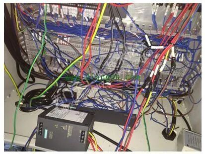 PLC systems have strict grounding requirements, ideally having an independent dedicated grounding system, and it is also important to ensure that other devices related to the PLC are reliably grounded.When multiple circuit grounding points are connected together, unexpected currents can arise, leading to logical errors or circuit damage.The reasons for different grounding potentials are usually due to grounding points being physically separated too far apart. When devices that are far apart are connected by communication cables or sensors, the current between the cables and ground can flow through the entire circuit. Even over short distances, the load current of large devices can cause variations in their ground potential, or generate unpredictable currents through electromagnetic effects.Between incorrect grounding points, there is a possibility of generating destructive currents in the circuit, which can damage equipment.PLC systems generally use a single-point grounding method. To enhance immunity to common-mode interference, shielded floating ground technology can be used for analog signals, where the shielding layer of the signal cable is grounded at one point, and the signal circuit is floating, with insulation resistance to ground not less than 50MΩ.2Interference Handling
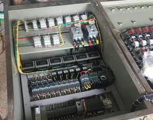 The industrial environment is often harsh, with many high and low-frequency interferences. These interferences are generally introduced into the PLC through cables connected to field devices.In addition to grounding measures, some anti-interference measures should be taken during the design selection and installation of cables:(1) Analog signals are small signals and are easily affected by external interference; therefore, double-shielded cables should be used;(2) High-speed pulse signals (such as pulse sensors, counting discs, etc.) should use shielded cables to prevent external interference and to prevent high-speed pulse signals from interfering with low-level signals;(3) Communication cables between PLCs generally have high frequencies and should preferably use cables provided by the manufacturer. If the requirements are not high, shielded twisted pair cables can be used;(4) Analog signal lines and DC signal lines should not be routed in the same cable tray as AC signal lines;(5) Shielded cables entering and exiting the control cabinet must be grounded and should connect directly to the equipment without passing through terminal blocks;(6) AC signals, DC signals, and analog signals should not share the same cable; power cables should be laid separately from signal cables;(7) During field maintenance, methods to resolve interference include using shielded cables for the affected lines and adding anti-interference filter code in the program.3Eliminating Inter-wire Capacitance to Avoid Malfunctions
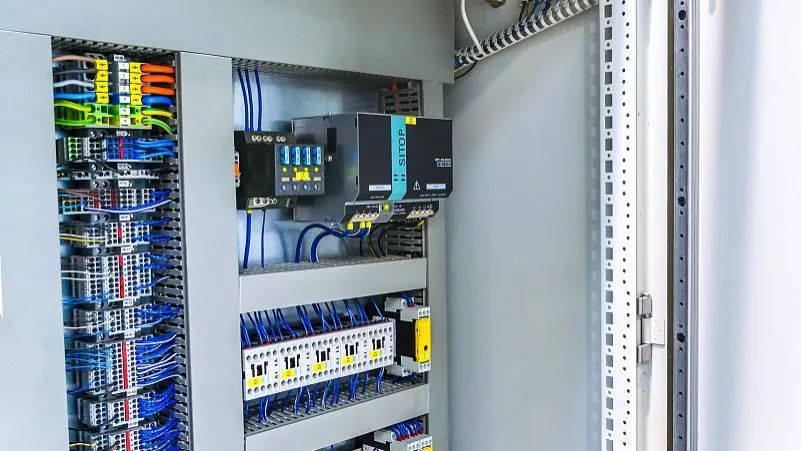 There is capacitance between the conductors of cables, and qualified cables can limit this capacitance to a certain range.Even with qualified cables, when the cable length exceeds a certain limit, the capacitance between wires can exceed the required values. When this cable is used for PLC inputs, inter-wire capacitance can cause PLC malfunctions, leading to many inexplicable phenomena.These phenomena mainly manifest as: correct wiring, but the PLC does not register input; inputs that should be present are missing, while inputs that should not be present are detected, indicating interference between PLC inputs. To resolve this issue, the following should be done:(1) Use twisted cables for the conductors;(2) Minimize the length of the cables used;(3) Separate cables for inputs that interfere with each other;(4) Use shielded cables.4Selection of Output Modules
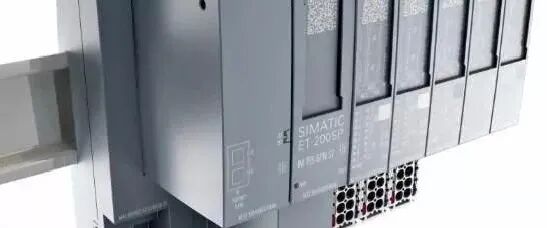 Output modules are divided into transistor, bidirectional thyristor, and contact types:(1) Transistor type has the fastest switching speed (generally 0.2ms), but the smallest load capacity, about 0.2~0.3A, 24VDC, suitable for fast switching and signal connection devices, generally connected to frequency converters, DC devices, etc. Attention should be paid to the impact of transistor leakage current on the load.(2) The advantage of thyristor type is that it has no contacts and possesses AC load characteristics, but the load capacity is not large.(3) Relay outputs have both AC and DC load characteristics, with large load capacity. In conventional control, relay contact type outputs are generally selected first, but the disadvantage is that the switching speed is slow, generally around 10ms, making it unsuitable for high-frequency switching applications.5Handling Overvoltage and Overcurrent in Frequency Converters
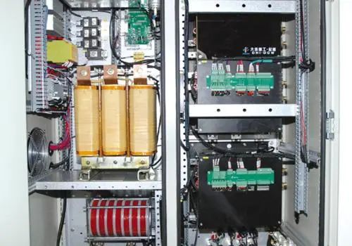 (1) Reducing the setpoint when the motor is decelerating causes the motor to enter regenerative braking mode, and the energy fed back to the frequency converter is also high. This energy is stored in the filter capacitor, causing the voltage across the capacitor to rise quickly, reaching the set value for DC overvoltage protection, causing the frequency converter to trip.The solution is to add a braking resistor externally to the frequency converter, using this resistor to dissipate the regenerative energy fed back to the DC side from the motor.(2) When a frequency converter drives multiple small motors, if one small motor experiences an overcurrent fault, the frequency converter will trigger an overcurrent fault alarm, causing it to trip, which in turn stops other normal small motors from working.Solution: Install a 1:1 isolation transformer on the output side of the frequency converter. When one or several small motors experience an overcurrent fault, the fault current will impact the transformer instead of the frequency converter, thus preventing the frequency converter from tripping. After testing, it worked well, and the previous issue of normal motors also stopping has not occurred.6Labeling Inputs and Outputs for Easy MaintenancePLC controls a complex system, and what can be seen are two staggered rows of input and output relay terminal blocks, corresponding indicator lights, and PLC numbers, resembling an integrated circuit with dozens of pins. Anyone who does not refer to the schematic to troubleshoot faulty equipment will be at a loss, and the speed of fault finding will be particularly slow. In light of this, we create a table based on the electrical schematic, which is posted on the control console or control cabinet, indicating the number of each PLC input and output terminal along with the corresponding electrical symbols and Chinese names, similar to the function descriptions of the pins of an integrated circuit.With this input-output table, electricians familiar with the operation process or the ladder diagram of this equipment can begin troubleshooting.However, for those who are not familiar with the operation process and cannot read the ladder diagram, another table needs to be created: the PLC input-output logic function table. This table actually explains the logical correspondence between the input circuits (triggering components, associated components) and output circuits (executing components) during most operational processes.Practical experience shows that if you can skillfully use the input-output correspondence table and the input-output logic function table, you can troubleshoot electrical faults without needing diagrams, making it easy and straightforward.7Inferring Faults Through Program Logic
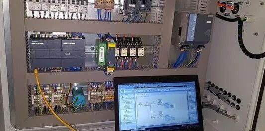 Currently, there are many types of PLCs commonly used in industry. For low-end PLCs, the ladder diagram instructions are quite similar, while for mid to high-end models, such as the S7-300, many programs are written in table language.A practical ladder diagram must have Chinese symbol annotations; otherwise, it is difficult to read. If you can roughly understand the equipment process or operation before looking at the ladder diagram, it will be easier to comprehend.When performing electrical fault analysis, the reverse lookup method or reverse inference method is generally used, which involves finding the corresponding PLC output relay from the fault point based on the input-output correspondence table and starting to trace back the logical relationships that satisfy its action.Experience shows that once a problem is identified, the fault can generally be eliminated, as it is rare for two or more fault points to occur simultaneously in the equipment.8Judging PLC Self-Faults
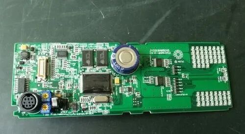 Generally speaking, PLCs are extremely reliable devices with a very low failure rate. The probability of hardware damage to PLCs, CPUs, or software errors is almost zero. PLC input points are unlikely to be damaged unless caused by strong electrical intrusion, and the normally open contacts of PLC output relays have a long lifespan unless there is a short circuit in the peripheral load or unreasonable design that exceeds the rated load current.Therefore, when searching for electrical fault points, the focus should be on the peripheral electrical components controlled by the PLC, rather than always suspecting issues with the PLC hardware or program. This is crucial for quickly repairing faulty equipment and restoring production.Thus, the electrical fault troubleshooting of PLC control circuits should focus not on the PLC itself, but on the peripheral electrical components in the control circuit.9Fully and Reasonably Utilize Software and Hardware Resources
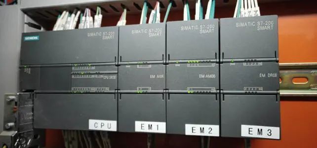 (1) Instructions that do not participate in control loops or have already been executed before the loop should not be input into the PLC;(2) When multiple instructions control a task, they can be connected in parallel externally before being input into a single input point;(3) Try to utilize the internal functional soft components of the PLC, fully utilize intermediate states, making the program coherent and easy to develop. This also reduces hardware investment and lowers costs;(4) If conditions permit, it is best to isolate each output for easier control and inspection, also protecting other output circuits; when one output point fails, it will only lead to the corresponding output circuit going out of control;(5) If the output is for forward/reverse control loads, not only should interlocks be implemented in the PLC internal program, but external measures should also be taken to prevent the load from acting in both directions;(6) Emergency stops for the PLC should use external switches to ensure safety.10Other Considerations
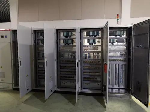 (1) Do not connect AC power lines to input terminals to avoid damaging the PLC;(2) Ground terminals should be independently grounded and not connected in series with other equipment; the cross-sectional area of the grounding wire should not be less than 2mm²;(3) Auxiliary power supplies have a small power capacity and can only drive low-power devices (such as photoelectric sensors, etc.);(4) Some PLCs have a limited number of occupied points (i.e., empty address terminal blocks), do not connect wires to them;(5) When there is no protection in the PLC output circuit, protective devices such as fuses should be used in the external circuit to prevent damage from load short circuits.
Disclaimer: This article is a network reprint, and the copyright belongs to the original author. If there are any copyright issues, please contact for deletion! The content of the article only represents the author’s personal views, and reprinting does not imply that this platform agrees with or holds the same views.

Recommended Classic Public Account
Add WeChat: 15311423147
Apply to join Mechanical Engineer WeChat Group!
Enter the public accountBottom Menu Bar
View classic design materials and industry articles!