Speed Control of G120 Frequency Converter
This example demonstrates speed control of the G120 frequency converter via PROFINET.
The S7-1500 PLC’s CPU1511-1 PN controls the G120 frequency converter for speed regulation via PROFINET.
Steps and Analysis:
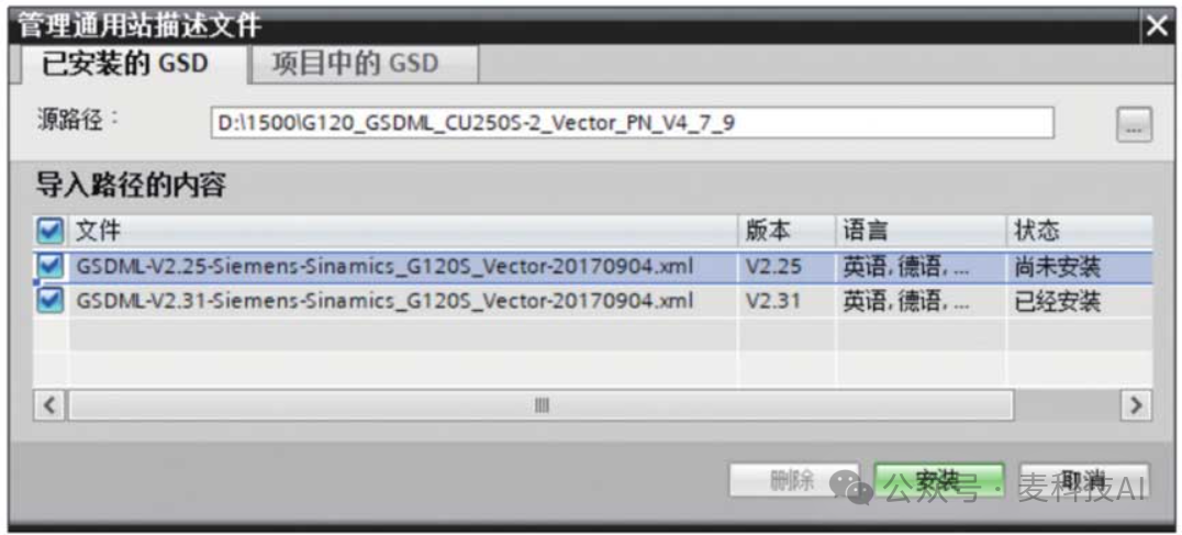
(1) Find the GSD file for the G120 frequency converter on Siemens’ website and import it into TIA Portal, as shown in the figure.
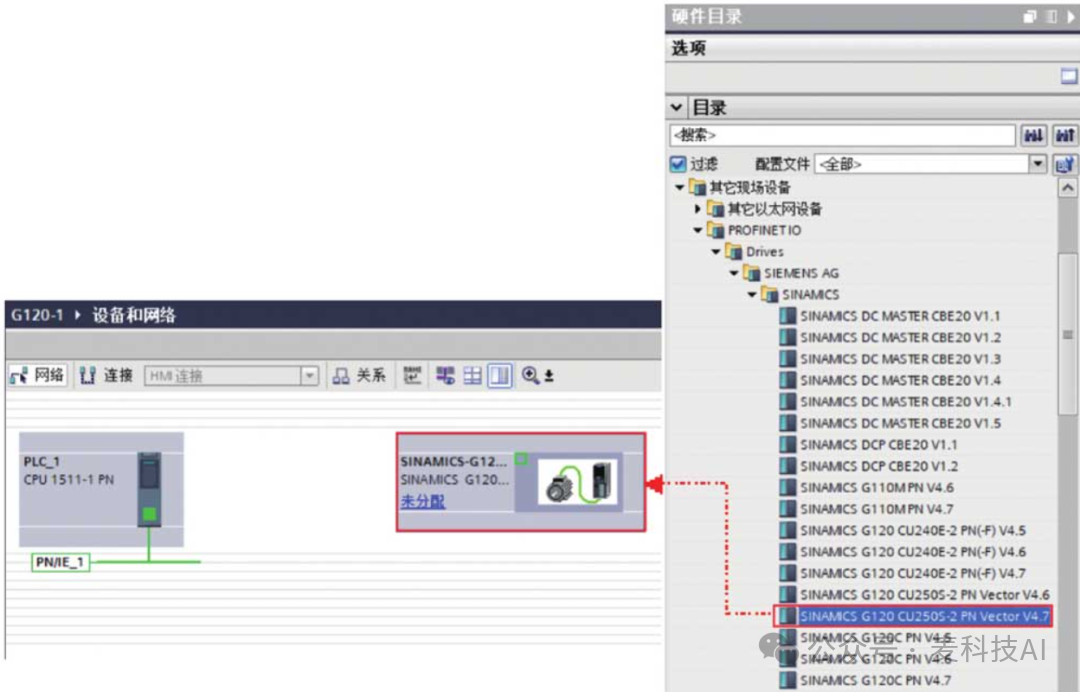
Add the G120 frequency converter in the network view (this example uses SINAMICS G120 CU2505-2 PN Vector V4.7), as shown in the figure.
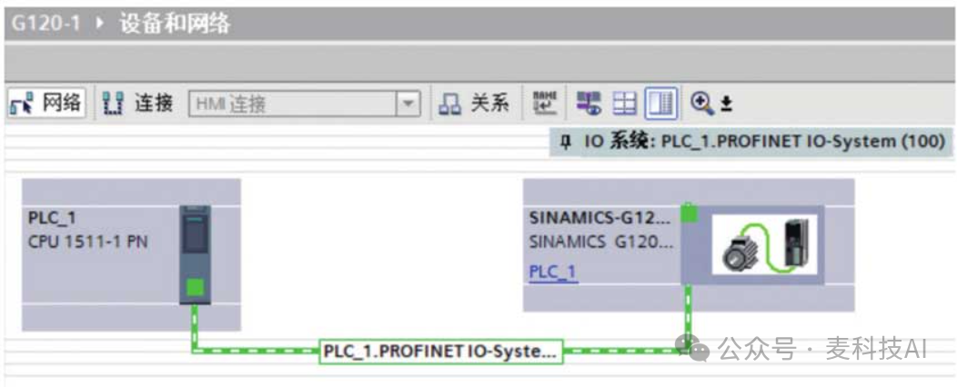
Connect the network as shown in the figure.
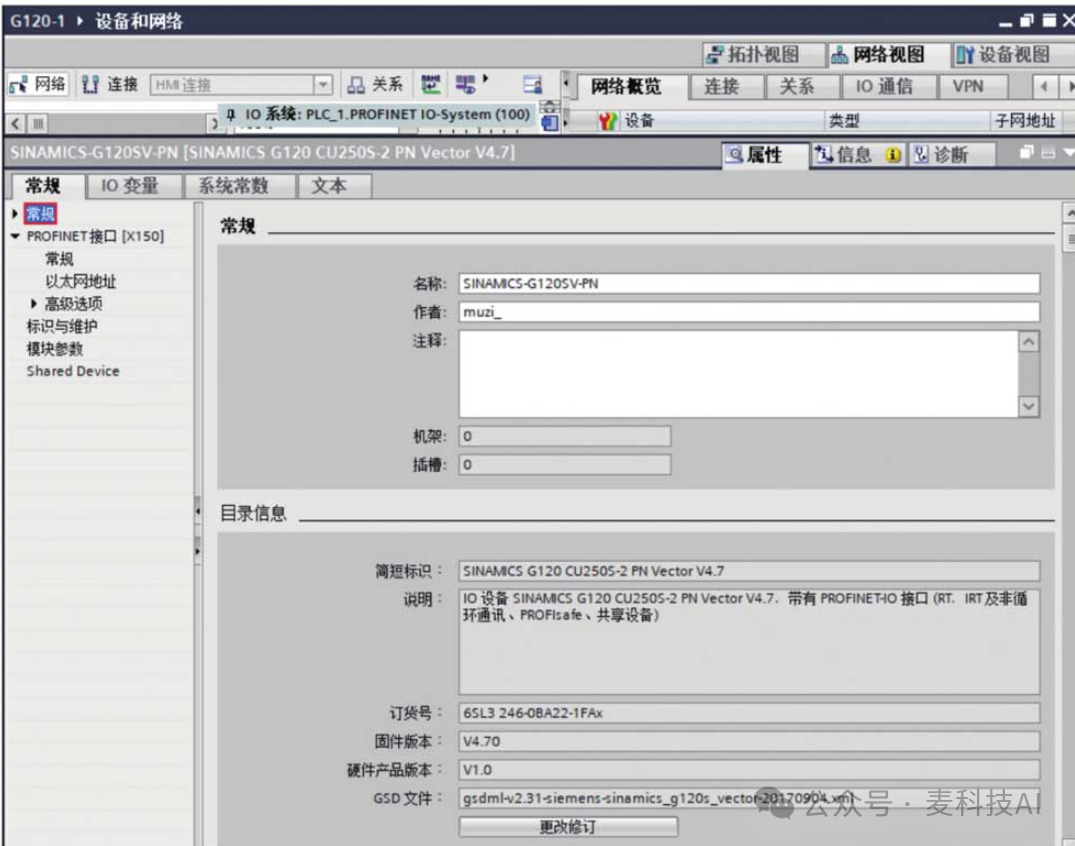
Set the general parameters of the G120 frequency converter as shown in the figure.
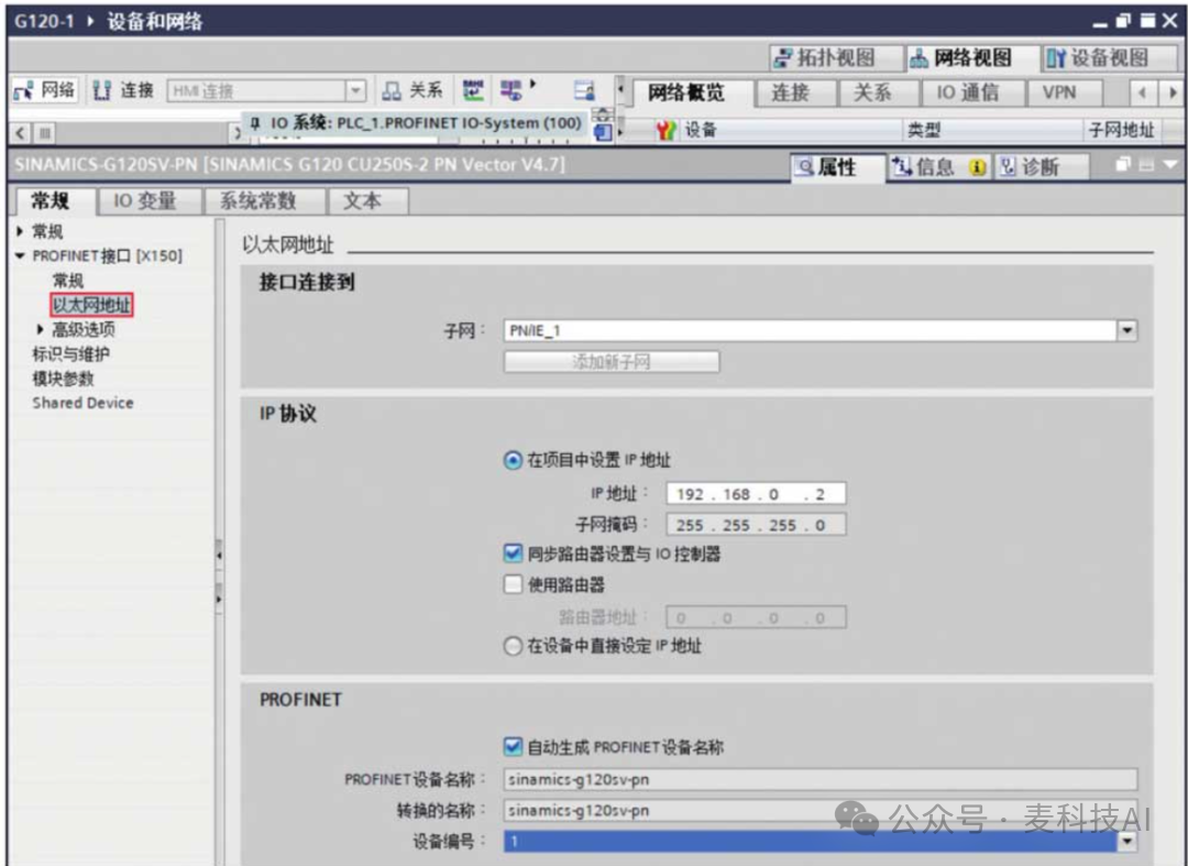
Set the IP address and PROFINET device name of the G120 frequency converter as shown in the figure.
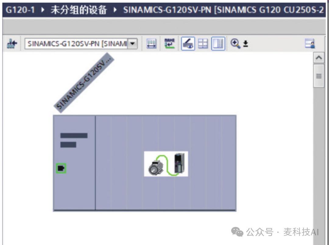
Overview of the G120 frequency converter as shown in the figure.
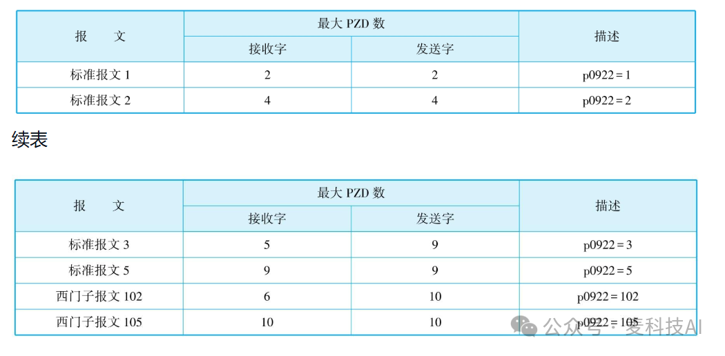
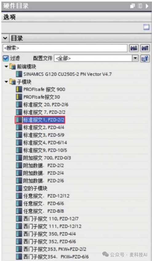
Select “Standard Message 1, PZD2/2” from the numerous message protocols, as shown in the figure.
The figure shows the completed G120 frequency converter with Standard Message 1.
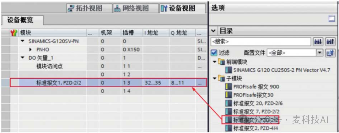
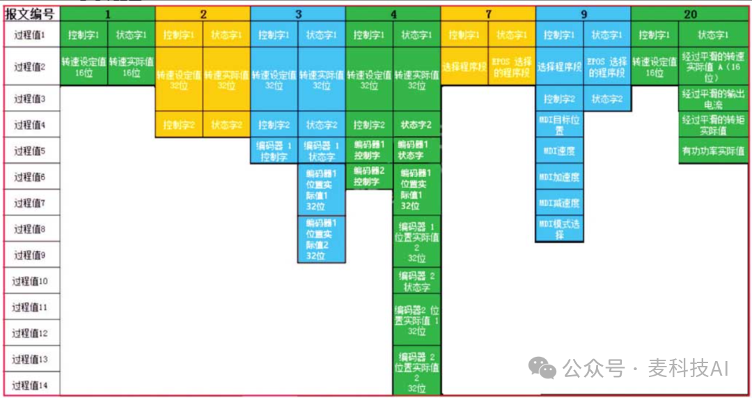
After configuring the G120 frequency converter, its I/O addresses are IB32 to IB35 and QB8 to QB11. According to the G120 standard message shown in the figure, the control word 1 corresponds to address QW8, the status word 1 corresponds to address IW32, the speed setpoint (16-bit) corresponds to address QW34, and the actual speed value (16-bit) corresponds to address IW10.
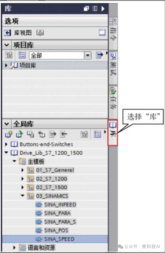
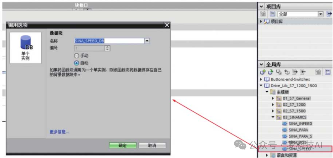
(2) Select “Library” as shown in the figure, and drag the SINA_SPEED (FB285) function block from DriveLib_S71500_V13 into the main program OB1, as it is a function block (FB), so a DB needs to be called, as shown in the figure.
The figure shows the SINA_SPEED (FB285) function block. The main parameter descriptions of the SINA_SPEED (FB285) function block are as follows. EnableAxis: Bool type, motor enable, runs when set to 1. AckError: Bool type, error reset. SpeedSp: Real type, speed of the frequency converter.
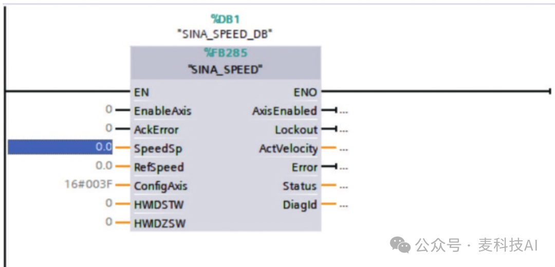
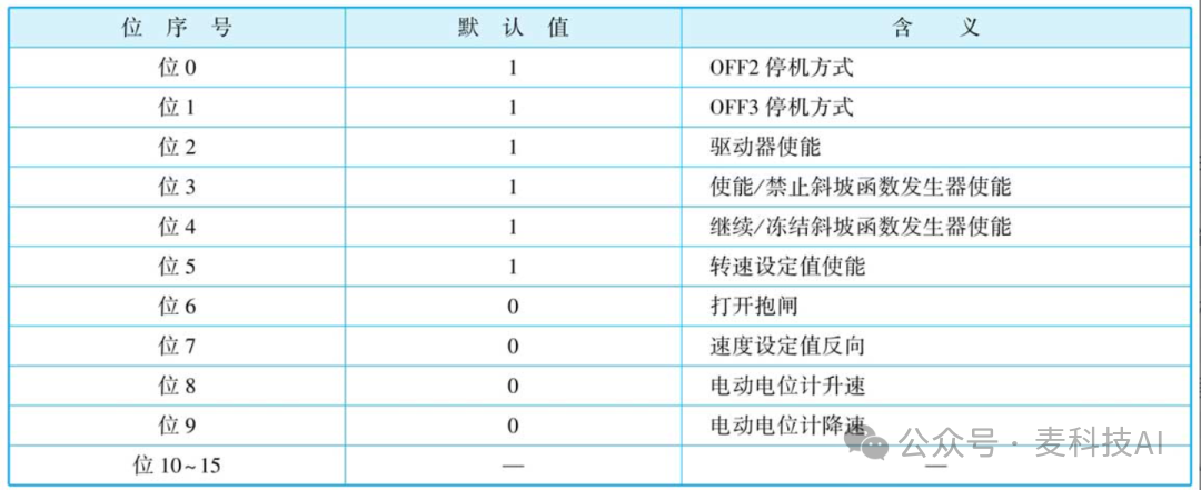
RefSpeed: Real type, reference speed of the frequency converter, which is a benchmark value, meaning that a maximum speed reference value is set. If RefSpeed is set to 1500 and SpeedSp is set to 1500, it corresponds to a frequency of 50Hz. If RefSpeed is set to 1000 and SpeedSp is set to 1000, it also corresponds to a frequency of 50Hz. ConfigAxis: Word type, a configuration parameter, with some parameters mainly used to control forward/reverse rotation, generally 16#003F for forward, 16#0C7F for reverse. The control description for each bit of ConfigAxis is shown in the table.
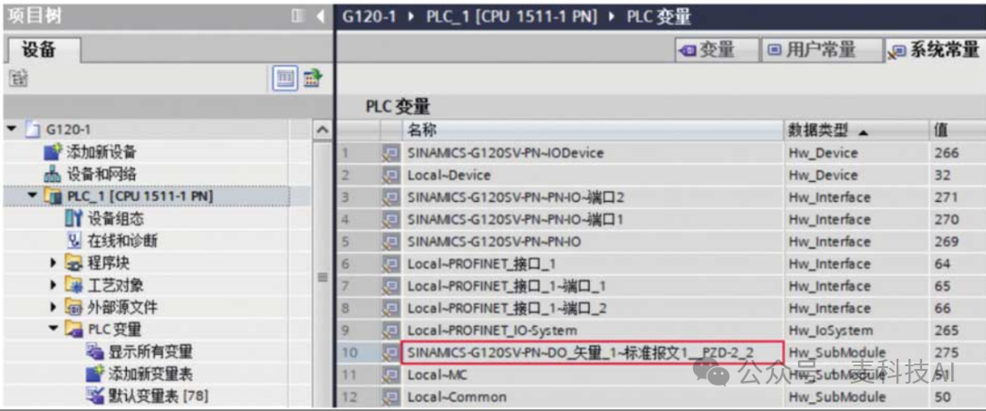
HWIDSTW and HWIDZSW: Hardware identifiers used to determine which frequency converter to communicate with. They need to be found in the PLC variables: first, find the corresponding frequency converter with the suffix “Standard Message 1_PZD-2_2” in the system constants, and then drag it directly into the program, as shown in the figure.
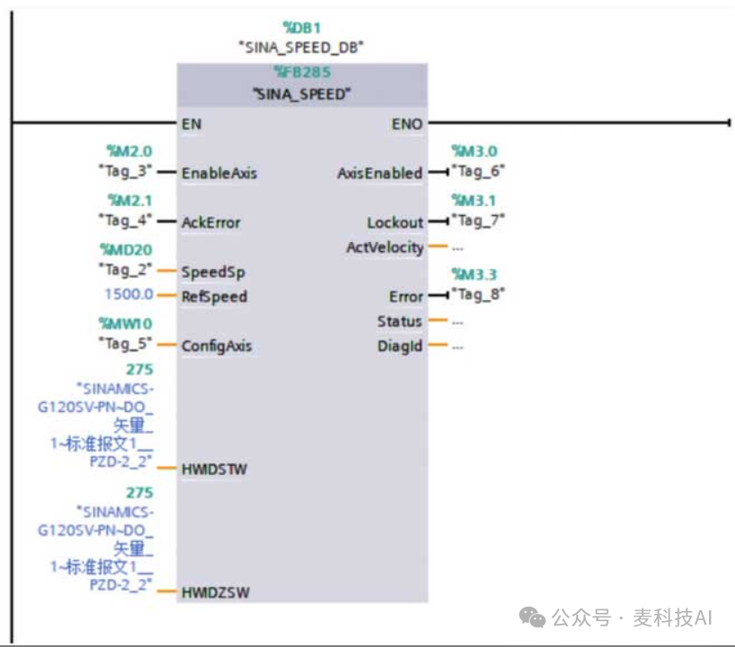
AxisEnabled: Bool type, the drive is enabled, normally enabled, after the motor starts running, the value becomes 1. Lockout: Bool type, the drive is in a prohibited state. ActVelocity: Real type, actual speed [rpm]. Error: Bool type, 1 = error exists, indicating an anomaly. Status: Int type, 16#7002, no error, function block is executing; 16#8401, drive error; 16#8402, drive prohibited from starting; 16#8600, DPRD_DAT error; 16#8601, DPWR_DAT error. Diagid: Word type, communication error, an error occurred during SFB call execution. The figure shows the completed SINA_SPEED (FB285) function block.
(3) The G120 frequency converter also needs to modify the corresponding message parameters, i.e., P0922 PROFIdrive PZD message selection “Standard Message 1, PZD-2/2”.
Speed Control of V90 Servo Drive
This example demonstrates speed control of the V90 servo drive via PROFINET.
The S7-1500 PLC’s CPU1511-1 PN controls the V90 servo drive for speed regulation via PROFINET.
Steps and Analysis:
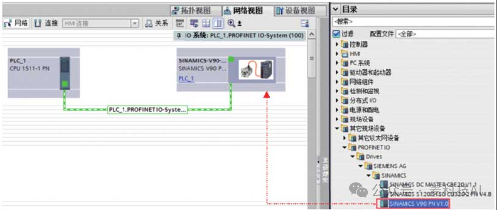
(1) Find the GSD file for the V90 servo drive on Siemens’ website and import it into TIA Portal. Add the V90 device (this example uses SINAMICS V90 PN V1.0) in the network view as shown in the figure.
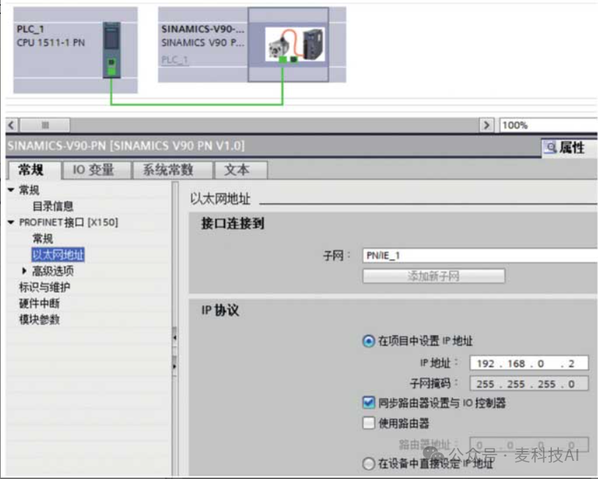
As shown in the figure, establish the network connection between the V90 and the S7-1500 PLC, and set the IP addresses of both the S7-1500 PLC and the V90, ensuring that both IP addresses are in the same subnet.
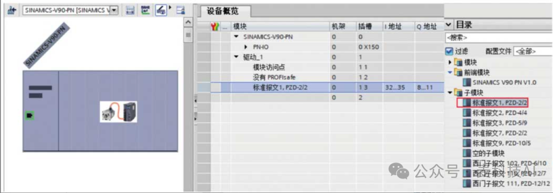
In the “Device Overview”, set the control message to “Standard Message 1, PZD-2/2”, as shown in the figure.
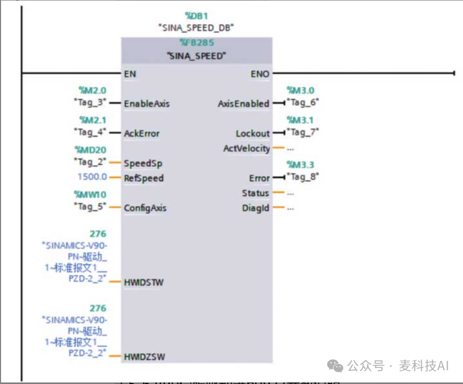
(2) In OB1, drag the SINA_SPEED (FB285) function block from DriveLib_S7_1200_1500 (this function block can only be used with Standard Message 1) into the programming network for speed control, as shown in the figure. The only difference is that the HWIDSTW and HWIDZSW values are different and need to be modified to “SINAMICS-V90-PN-Drive_1-Standard Message 1_PZD-2_2”, which is 276.
(3) The table shows the parameter description for the V90 servo drive P0922.