How to Design a Chip from Scratch?
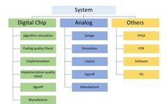
How to Design a Chip from Scratch?

Source: Content from “Mo Shang Feng Qi Lu Kan IC“, Author: Mo Shang Feng Qi Lu, thank you.. With support from various parties, integrated circuits have become a hot topic of the era, and there are numerous articles discussing the complexity and difficulties of chip design. I plan to clarify the chip design process from … Read more

Fundamentals of Digital Circuit Design: From Verilog to Tapeout

We will progress together, remember to mark me as a star in the upper right corner~ Course Preview is about to start☟ 1 Course Preview Time February 22, 2020, 7 PM QQ Group Video Live Broadcast 2 Instructor Qualifications Both Bachelor’s and Master’s degrees from Fudan University in Microelectronics. Has been engaged in digital integrated … Read more

China’s First Large-Scale Fully Asynchronous Chip Successfully Taped Out

China's First Large-Scale Fully Asynchronous Chip Successfully Taped Out

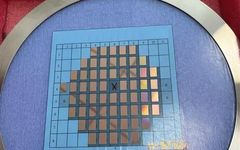
Recently, the first large-scale fully asynchronous circuit (Asynchronous Circuit) chip designed by the asynchronous circuits and systems team led by Associate Professor He Anping from Lanzhou University’s School of Information Science and Engineering has been successfully taped out. Fully asynchronous circuit chip (Image from: Lanzhou University) This chip consists of 120 chips named LZU_GERM, with … Read more

Embedded Interview Guide: Basic Circuit Knowledge

Embedded Interview Guide: Basic Circuit Knowledge

01 Basics of Analog Circuits 1.1 Basic Components (Characteristics, Applications, Selection): Resistors: Voltage division, current limiting, pull-up/pull-down, impedance matching. Understand Ohm’s law, power calculation, packaging and power relationship. Reading color-coded resistors. Capacitors: AC coupling, filtering (decoupling/bypass), energy storage, timing. Understand capacitive reactance, charging and discharging processes, ESR, dielectric types (ceramic, electrolytic, tantalum capacitors) and application … Read more

Basic Syntax of FPGA

Basic Syntax of FPGA

Input and Output Signals The input signals of the input module, such as input rst. The output signals of the output module, such as output en. The bidirectional signals of the inout module. Signal Types wire signal, generally used in assign statements. reg register, generally used in always blocks. Module Structure The content of each … Read more

What is the Three-Year Foundation in the FPGA Industry?

What is the Three-Year Foundation in the FPGA Industry?

Hello everyone, today we are going to discuss a common topic in the FPGA community – the “three-year foundation.” Yes, that infamous “three-year rule” that terrifies countless beginners and makes experts smile. Some say it’s a superstition, while others claim it’s a truth. So, the question arises: is this concept reliable? Today, we will delve … Read more

Understanding Timing Diagrams in Embedded Development

Understanding Timing Diagrams in Embedded Development

Follow usLearn Embedded Together and grow together The core of a timing diagram is the relationship between time and the level changes. Time progresses from left to right, and levels are represented as high or low, typically denoted by 0 and 1. A timing diagram helps us understand the changes of various signals in a … Read more

What are the Execution Modes of FPGA

What are the Execution Modes of FPGA

The execution modes of FPGA are download mode and programming mode. 1. FPGA is a type of digital integrated circuit chip, known as “Field Programmable Gate Array”. An important feature of FPGA is its programmability, which allows users to specify a particular digital circuit through programming. The components of FPGA include CLB (Configurable Logic Block), … Read more

Confusions in Learning FPGA

Confusions in Learning FPGA

Don’t let these misconceptions hinder your growth curve At two in the morning, the lights in the lab are still on. You stare at the flashing timing error messages on the screen, having modified the Verilog code for the 17th time, yet the development board remains silent as a stone. The coffee beside you has … Read more

Why Do SPI and Other Signal Outputs Require a 22 or 33 Ohm Resistor?

Why Do SPI and Other Signal Outputs Require a 22 or 33 Ohm Resistor?

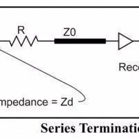
When a microcontroller or FPGA sends SPI control signals to a phase-locked loop (PLL) chip, it often requires a series connection of a 22 ohm or 33 ohm resistor. What is the reasoning behind this? Impedance discontinuities can cause electromagnetic wave reflections, which in turn can lead to signal distortion. Therefore, impedance matching is often … Read more