
Click the blue text above to follow us
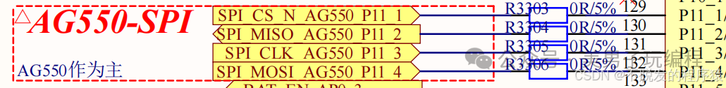
The main reason for adding a 22Ω or 33Ω resistor in series when a microcontroller uses SPI to connect to a sensor or controller is to suppress reflections and ringing.
1
Principle of Reflection and Source Matching
In high-speed digital signal transmission, when the signal driver (such as a microcontroller or FPGA) outputs to the load (such as a sensor), it passes through the transmission line on the PCB.
If the characteristic impedance Z0 of the transmission line does not match the output impedance Zd of the driver, it will cause signal reflections.
Reflections can lead to distortion of the signal waveform, causing ringing, overshoot, and other issues, particularly noticeable at the rising and falling edges of the signal.
Source matching is achieved by placing a resistor R in series at the driver end, so that the output impedance of the signal source plus the series resistor matches the transmission line impedance Z0, thereby reducing reflections.
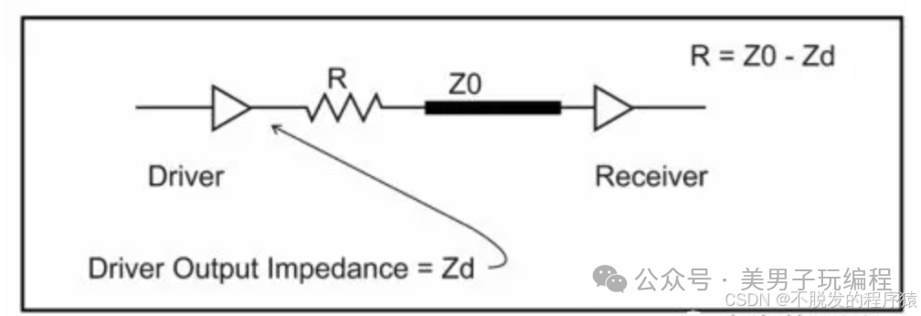
Therefore, by placing a resistor R=Z0−Zd in series at the source end, impedance matching can be optimized, effectively suppressing reflections.
The 22Ω or 33Ω resistors are typically reasonable values derived from experience, suitable for most digital circuits.
2
Matching in Digital Circuits
In RF circuits, passive components such as inductors and capacitors are often used for matching, a process known as conjugate matching.
The goal is to maximize the transmission of signal energy to the load, often requiring precise 50Ω matching.
However, matching in digital circuits is relatively simple; the goal is to suppress reflections rather than maximize energy transfer, thus resistors are typically used for source matching.
The resistor matching method not only simplifies design but also provides a reasonable balance between signal integrity and practical operating costs.
3
Why Choose 22Ω or 33Ω?
In practice, the output impedance Zd of digital devices is often not ideal and can vary significantly.
For example, even chips of the same model can have different output impedances under different operating conditions.
Some theoretical formulas mentioned in forums and literature, such as Zo = (Vdd-VOH) / IOH and Zo = VOL/IOL, can only serve as references and not absolute calculation standards.
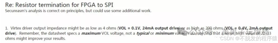
Based on experience, 22Ω or 33Ω resistors can often reduce ringing and reflections in most cases, which is why they are widely adopted.
4
Tuning in Actual Design
In actual designs, due to differences in devices and PCB layouts, resistor values may need fine-tuning; therefore, design typically reserves resistor pads on the PCB.
During debugging, one can use an oscilloscope to observe waveforms with different resistor values, gradually adjusting the resistor until the ringing and overshoot of the waveform are minimized. This provides flexibility for subsequent debugging and optimization at the early design stage.
Adding 22Ω or 33Ω resistors reflects the importance of “source matching” in digital circuit design.Through reasonable resistor matching, ringing and reflections can be suppressed, ensuring signal stability and reliability.