For more experience sharing, follow RF Engineer
When a microcontroller or FPGA sends SPI control signals to a phase-locked loop chip, it often requires a series connection of a 22 ohm or 33 ohm resistor. What is the reason for this?
Impedance discontinuities can cause electromagnetic wave reflections, which in turn lead to signal distortion. Therefore, impedance matching is often involved in high-speed digital circuit design. However, this matching is different in operation from RF matching.
In RF matching, inductors and capacitors are typically used to reduce reflections, whereas in digital circuits, resistors are generally used for matching.
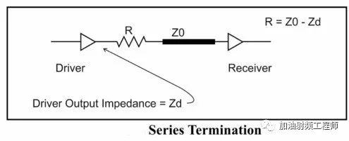
In digital circuits, source matching is one of the matching methods. The aforementioned series resistor in the signal path is a typical example of source matching. Assuming the output resistance of the digital circuit is Zd, and the characteristic impedance of the transmission line is Z0, then the series resistor is given by R=Z0-Zd.
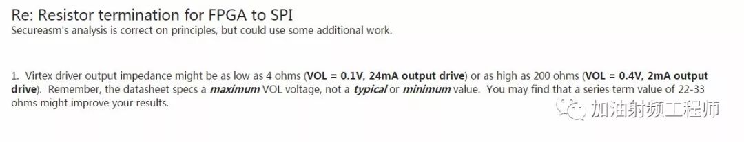
On forums, it has been mentioned that the output resistance of digital circuits can be calculated using Zo = (Vdd-VOH) / IOH and Zo = VOL/IOL. However, in practice, this is not ideal.
As mentioned in (2), even for the same model of device, the values can vary significantly.
Therefore, in practical operations, it is advisable to leave a position on the circuit to change the resistor value while testing with an oscilloscope to observe when the ringing in the waveform disappears.
References:
(1) https://www.physicsforums.com/threads/how-to-determine-the-output-impedance-of-cmos-gates.433643/
Some images and text are sourced from the internet. If there is any infringement, please leave a message in the background, and I will delete it immediately. Thank you!
Long press the image to follow the WeChat account