Welcome FPGA engineers to join the official WeChat technical group.
ClickBlue WordsFollow us at FPGA Home – the best and largest pure FPGA engineer community in China
About Reset
Numbers
In digital circuits, the circuit starts up through reset, which acts like a “pacemaker” for digital circuits. There are mainly three ways:
1
No Reset: Naturally strong, starts up when powered on;
2
Asynchronous Reset: A kind-hearted person passes by and kicks it casually, triggering it without any preparation; it can be revived at any time;
3
Synchronous Reset: A professional rescue team, pressing on the chest, not letting go until they hear the “bang bang” sound. Very critical, must hold for a while.
No Reset
I’ve never seen code written like this, actually without a reset. Teachers always say that digital circuits cannot do without resets. Without a definite initial value, how can the circuit work?
Actually, there’s no need to worry. After powering on the FPGA, the initial value of the registers defaults to “0”; of course, it can also be manually assigned an initial value. Below is the code without reset:
reg [7:0] my_register;
always @(posedge clk) begin
my_register <= data_in;
end
If there is no reset signal, many resources are saved, and the compilation and routing time is greatly reduced. If the scale is large, it is also helpful for improving overall design performance. However, in digital circuit design, we rarely do not use reset circuits. Instead, we often take advantage of this feature of FPGA to generate internal reset circuits ourselves.
Asynchronous Reset
Asynchronous reset circuit description: Add the reset signal to the sensitivity list in the always statement to implement asynchronous reset.
reg [7:0] my_register;
always @(posedge clk, posedge rst) begin
if(rst)
my_register <= 8’h0;
else
my_register <= data_in;
end
The disadvantages of asynchronous reset:
Asynchronous reset has strict requirements for the reset signal; otherwise, a random glitch could reset the circuit.
In addition, the asynchronous reset signal relies on the conduction delay within the FPGA, so under slight voltage or temperature differences, the design may output errors, and the portability of the design is also poor. Didn’t we just say that a casual kick can trigger it; sometimes you can feel it, sometimes you can’t. In winter, wearing a thick cotton jacket, you have to exert a lot of effort to remind it.
Because the delays for different registers are different, it easily leads to intermittent design issues. How to understand this?
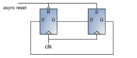
As shown in the figure, a 2-bit shift register forms a ring. After reset, the left register is cleared to zero, the right register is set, and both are triggered on the same rising edge. Therefore, if the rising edge of the left register comes when the reset signal has already been released, but the right register is still in reset state, the data will be incorrect.
The advantages of asynchronous reset:
Asynchronous reset does not depend on the clock. Therefore, if the clock is an external input and may be lost, such as in power-saving mode, only asynchronous reset can be used.
Another advantage is faster physical implementation of the design. Compared to synchronous reset, asynchronous reset has looser timing constraints, allowing layout and routing tools to meet constraint conditions in less time.
Synchronous Reset
Synchronous reset is very professional, leaving no room for error, and as its name suggests, it only occurs on the valid edge of the clock. Therefore, an effective synchronous signal must last for at least one clock cycle (if you can’t wake them up, they won’t stop). Since it is only valid on the effective edge of the clock, it can filter out glitches on the reset signal, greatly improving circuit reliability.
reg [7:0] my_register;
always @(posedge clk) begin
if(rst)
my_register <= 8’h0;
else
my_register <= data_in;
end
So, to summarize, its advantage is that it “makes up for all the shortcomings of asynchronous reset,” while its disadvantage is that it “doesn’t have the advantages of asynchronous reset.” This summary is simple enough, right?
Conclusion
We have familiarized ourselves with the three reset methods and understood their characteristics, so let’s summarize how to use them in our designs.
Try to use synchronous reset if your scale is not particularly large; although it occupies slightly more routing resources, it is still helpful for system reliability.
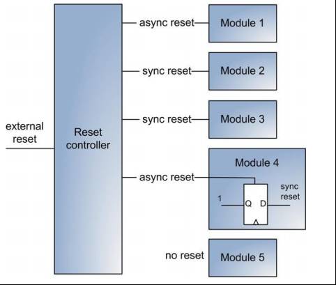
When the scale is large, consider a mixed reset method. In what situations? For example, when there are multiple IP cores and functional modules in the design, requiring different reset methods, mixed reset methods are necessary. Additionally, circuit delays in large circuits may exceed 10ns between two modules; if the clock cycle is 3ns, it requires 3 clock cycles to pass. Therefore, achieving complete synchronization in large designs is very challenging. As shown in the figure is a complex mixed reset tree, utilizing various reset methods.

Welcome engineers in FPGA and embedded systems to follow our public account.

China’s Largest FPGA WeChat Technical Group
Welcome everyone to join the national FPGA WeChat technical group. This group has tens of thousands of engineers, a group of technology-loving engineers where FPGA engineers help and share with each other, creating a strong technical atmosphere!Quickly call your friends to join!!

Just press with your finger to join the national FPGA technical group.
FPGA Home Components City
Advantageous component services, please scan to contact the group owner: Jin Juan Email: [email protected] Welcome to recommend to procurement
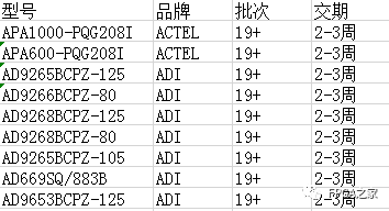
ACTEL, AD part of the advantages for ordering (operating the full series):
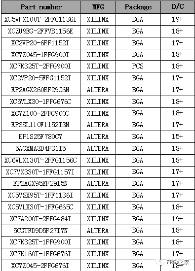
XILINX, ALTERA advantageous stock or ordering (operating the full series):
(The above devices are part of the models, for more models please consult group owner Jin Juan)
Service concept: FPGA Home Components City aims to facilitate engineers to quickly and conveniently purchase component services. After years of dedicated service, our customer service covers large listed companies, military research units, and small and medium enterprises. Our greatest advantage is emphasizing the service-first concept, and achieving fast delivery and favorable prices!
Directly operated brands: Xilinx, ALTERA, ADI, TI, NXP, ST, E2V, Micron, and over a hundred component brands, especially adept at handling components subject to embargoes from the US and EU.Engineers are welcome to recommend us to procurement or consult us directly!We will continue to provide the best service in the industry!

Official thanks to brands in the FPGA technical group: Xilinx, Intel (Altera), Microsemi (Actel), Lattice, Vantis, Quicklogic, Lucent, etc.