Scan to follow "Learn Embedded Together", learn together, grow together.
1. What are the differences between STM32F1 and F4?
Different cores: F1 has Cortex-M3 core, F4 has Cortex-M4 core;
Different clock frequencies: F1 has a clock frequency of 72MHz, F4 has a clock frequency of 168MHz;
Floating-point operations: F1 has no floating-point unit, F4 does;
Functional performance: F4 has richer peripherals and stronger functions than F1, such as GPIO toggle rate, pull-up and pull-down resistor configuration, ADC accuracy, etc.;
Memory size: F1 has a maximum internal SRAM of 64K, while F4 has 192K (112+64+16).
2. Describe the STM32 startup process
Reference: Detailed analysis of STM32 startup process
Set the Boot pin to find the initial address
Initialize the stack pointer __initial_sp
Point to the reset program Reset_Handler
Set the exception interrupt HardFault_Handler
Set the system clock SystemInit
Call C library function _main
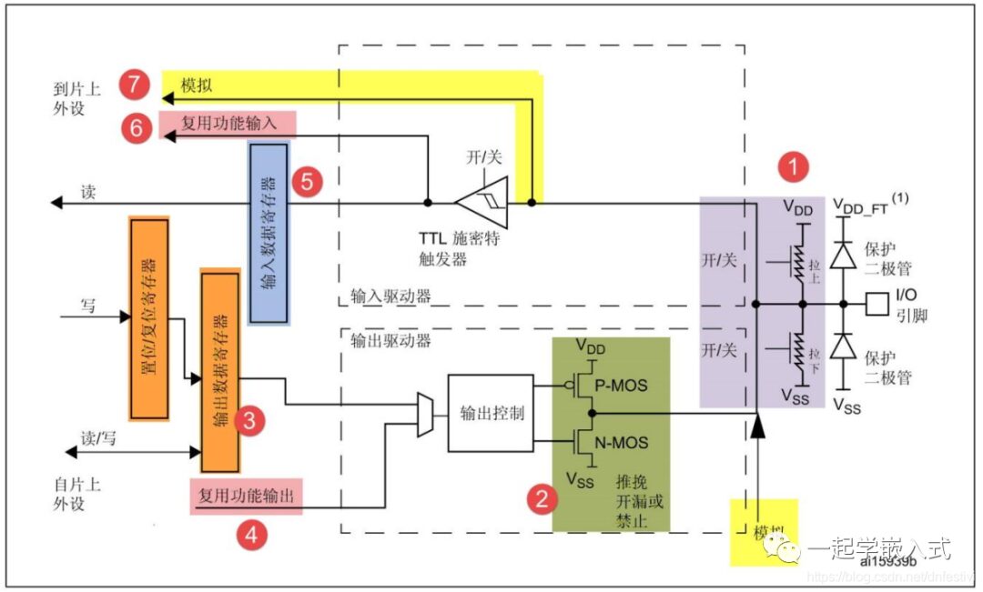
3. Introduce GPIO
Reference: Detailed explanation of STM32 microcontroller GPIO working principles
8 working modes of GPIO (gpio_init.GPIO_Mode):
(1) GPIO_Mode_AIN Analog Input (2) GPIO_Mode_IN_FLOATING Floating Input (3) GPIO_Mode_IPD Pull-down Input (4) GPIO_Mode_IPU Pull-up Input (5) GPIO_Mode_Out_OD Open Drain Output (6) GPIO_Mode_Out_PP Push-pull Output (7) GPIO_Mode_AF_OD Alternate Function Open Drain Output (8) GPIO_Mode_AF_PP Alternate Function Push-pull Output
APB2 is responsible for AD, I/O, advanced TIM, USART1.
APB1 is responsible for DA, USB, SPI, I2C, CAN, USART2345, general TIM, PWR
4. UART
Reference: Thorough understanding of UART communication
Synchronous communication: I2C half-duplex, SPI full-duplex
Asynchronous communication: RS485 half-duplex, RS232 full-duplex
-
Question 2: Serial port configuration
The general steps for serial port settings can be summarized as follows:
(1) Enable serial port clock, enable GPIO clock
(2) Reset the serial port
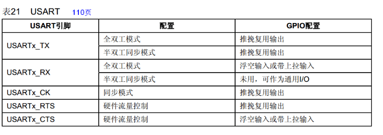
TX GPIO working mode: GPIO_Mode_AF_PP; // Alternate Function Push-pull Output
RX GPIO working mode: GPIO_Mode_IN_FLOATING; // Floating Input
(4) Serial port parameter initialization mainly includes: baud rate setting (115200), 8 data bits, 1 stop bit, no parity bit, no hardware flow control, transmit and receive mode.
(5) Enable interrupts and initialize NVIC (this step is only needed if interrupts need to be enabled)
(6) Enable the serial port
(7) Write interrupt handler function
-
Question 3: Main features of USART
(1) Full-duplex operation (independent receiving and sending data);
(2) In synchronous operation, it can be either master clock synchronized or slave clock synchronized;
(3) Independent high-precision baud rate generator, does not occupy timer/counter;
(4) Supports serial data frame structure with 5, 6, 7, 8, and 9 data bits, and 1 or 2 stop bits;
(5) Hardware-supported parity bit generation and checking;
(6) Data overflow detection;
(7) Frame error detection;
(8) Includes noise filter for detecting erroneous start bits and digital low-pass filter
(9) Three completely independent interrupts: TX complete, TX data register empty, RX complete;
(10) Supports multi-master communication mode;
(11) Supports double-speed asynchronous communication mode.
Application scenarios: GPS, Bluetooth, 4G modules
5. I2C
Reference: Comprehensive analysis of I2C communication protocol
Question 1: What are the three types of signals in I2C bus data transmission?
(1) Start signal: When SCL is high, SDA transitions from high to low, starting data transmission.
(2) Stop signal: When SCL is high, SDA transitions from low to high, ending data transmission.
(3) Acknowledge signal: The IC receiving data sends a specific low-level pulse to the sending IC after receiving 8 bits of data, indicating that the data has been received.
After the CPU sends a signal to the controlled unit, it waits for the controlled unit to send an acknowledgment signal. After receiving the acknowledgment signal, the CPU decides whether to continue transmitting the signal based on the actual situation. If no acknowledgment signal is received, it is judged that the controlled unit has malfunctioned.
Question 2: How to configure the I2C master mode port?
Hardware mode: Alternate Function Open Drain Output, neither pull-up nor pull-down. (Fast mode: 400 Kbit/s)
Software simulation: Push-pull output, configure pull-up resistors.
Question 3: What is the I2C arbitration mechanism?
The I2C arbitration mechanism is easily understood by the concept of