Introduction
Have you often heard others talk about PID control but found yourself confused or not understanding it at all?
Don’t worry, here comes a comprehensive guide to understanding PID!
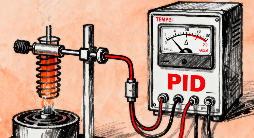
1. What is PID?
Imagine you are driving a car, and your goal is to stay on the center line of the road (setpoint).
- Your eyes are the sensors, constantly measuring how far the car is from the center line (current value).
- Your brain is the controller, deciding how much and how quickly to turn the steering wheel based on the distance from the center line.
- Your hands are the actuators, turning the steering wheel according to the brain’s instructions.
The PID algorithm is the decision-making model of this “brain”. It is not a single formula but a “smart decision package” that integrates three control strategies. Its core goal is: to make the current value (actual measurement) reach and maintain the setpoint (target value) as quickly, smoothly, and accurately as possible.
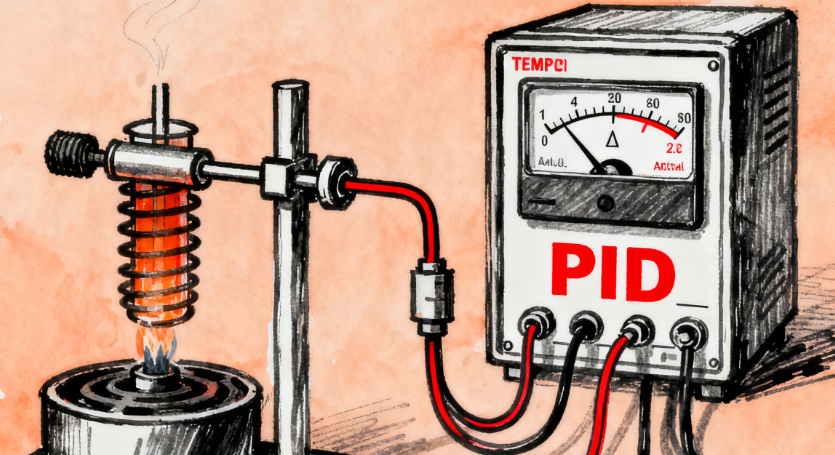

2. What are the differences between the three parameters P, I, and D?
Let’s use a simple example to understand the roles of these three parameters: controlling the water temperature in a kettle, aiming to maintain it at 80°C.
1. P – Proportional
- Function: The force applied is proportional to the current deviation.
- Working Principle: The effect of P is proportional to the current deviation (setpoint – current value).
- If the water temperature is currently 70°C, the deviation from the target is 10°C, and P will output a medium power to heat.
- If the water temperature drops to 60°C, the deviation is 20°C, and P will output a larger power to heat.
- If the water temperature is close to 80°C, only 1°C away, P will output a very small power.
- Advantages: Quick response, able to immediately react to deviations. It is the main force in control.
- Disadvantages: Static error exists. When the water temperature is close to 80°C, the deviation is small, and P outputs a small power. This small power may just offset the heat loss, causing the water temperature to stabilize at 79°C, unable to reach 80°C. This 1°C difference is the “static error”.
2. I – Integral
- Function: The accumulated deviation over time continuously works to eliminate static error.
- Working Principle: I accumulates all deviations over time. As long as there is a deviation (no matter how small), the output of I will continue to increase.
- Advantages: Eliminates static error. Returning to the kettle example, when the water temperature stabilizes at 79°C due to P, although the deviation is only 1°C, I will start accumulating this “+1°C” deviation. Over time, the output of I will gradually increase, providing additional “push” to the heater until the water temperature finally reaches 80°C, at which point the deviation is zero, and I stops accumulating, stabilizing the output.
- Disadvantages: Can lead to overshoot and oscillation. Because of the lag in I’s accumulation, when it acts, the water temperature may have already exceeded 80°C, causing the temperature to overshoot, then needing to cool down, resulting in fluctuations.
3. D – Derivative
- Function: Predicts the rate of change of future deviations and “hits the brakes” in advance.
- Working Principle: D focuses on the rate of change of the deviation. It does not consider how large the deviation is, only how quickly it is changing.
- Advantages: Suppresses overshoot and improves system stability. When the water temperature rises quickly and is about to exceed 80°C, even if the current deviation may still be positive (e.g., +0.5°C), D detects this “rapid change” trend and will produce a “reverse” suppressive effect (e.g., reducing heating power), like an experienced driver gently applying the brakes in advance to prevent overshooting.
- Disadvantages: Sensitive to noise. If the sensor signal has slight, rapid fluctuations, D may mistakenly interpret this as a drastic change, leading to unnecessary, drastic adjustments that could destabilize the system.
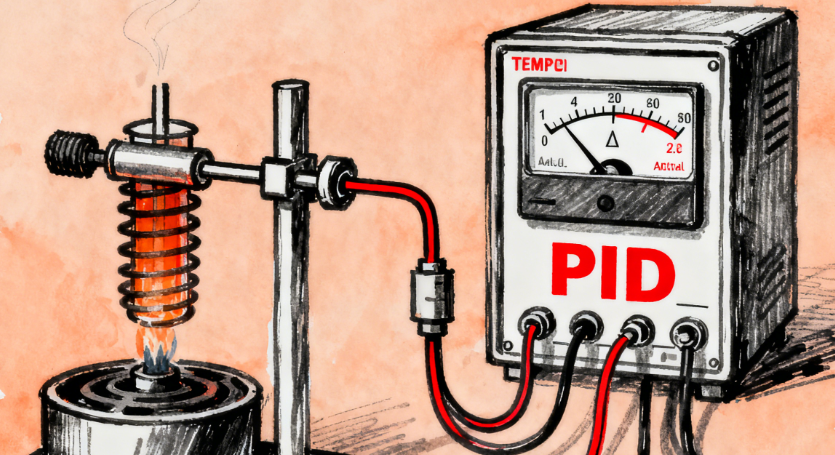

3. Application Case of PID in PLC Control
Case Study: Constant Pressure Water Supply System
-
Objective: Maintain the water pressure in the pipeline at a constant setpoint (e.g., 0.5MPa).
-
System Components:
- PLC: The controller running the PID program.
- Pressure Sensor: Installed on the pipeline, measuring water pressure in real-time (the “current value” for PID).
- Variable Frequency Drive: The actuator that receives signals from the PLC to adjust the speed of the water pump motor.
- Water Pump: The controlled object.
-
Control Process:
- Deviation = 0.5MPa (setpoint) – 0.3MPa (current value) = 0.2MPa.
- P Action: Based on the 0.2MPa deviation, output a basic control amount to run the variable frequency drive at a higher frequency.
- I Action: If the water pressure stabilizes at 0.48MPa (static error), I will accumulate this 0.02MPa deviation, gradually increasing the output frequency until the water pressure reaches 0.5MPa.
- D Action: When a user suddenly opens a faucet, the water pressure will drop rapidly. D detects this “rapid drop” trend and will instantly increase the output, allowing the water pump speed to rise quickly to counter the pressure drop, preventing the water pressure from falling too low.
- Set Target: The operator sets the target pressure to 0.5MPa on the HMI (Human-Machine Interface).
- Real-time Measurement: The pressure sensor sends the measured real-time water pressure (e.g., currently 0.3MPa) to the PLC’s analog input module via a 4-20mA signal.
- PID Calculation: The PID function block in the PLC performs calculations during each scan cycle:
- Output Control: The PID function block sends the calculated final result (a value) to the variable frequency drive through the PLC’s analog output module.
- Execution Adjustment: The variable frequency drive adjusts the water pump motor speed based on the received signal, thereby changing the water supply pressure.
- Continuous Cycle: This process repeats continuously, forming a closed-loop control, ensuring that regardless of changes in user water usage, the pipeline pressure remains stable around 0.5MPa.
In addition to constant pressure water supply, PID applications in PLCs are ubiquitous, such as:
- Temperature Control: Constant temperature furnaces, injection molding machine barrel temperatures.
- Speed Control: Conveyor belts, motor synchronization.
- Position Control: Servo motor precise positioning.
- Flow Control: Liquid flow in chemical pipelines.
This detailed explanation will help you thoroughly understand PID!
