Basic Input Instructions for Huichuan PLC Ladder Diagrams
The instructions for Huichuan PLC ladder diagrams are fundamentally consistent with those of other commonly used PLC brands. Below is a summary of some basic instructions based on the input effects in programming software.
LD—Load normally open contact instruction. The operand is of boolean type.
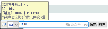
LDI—Load normally closed contact. The operand is of boolean type.
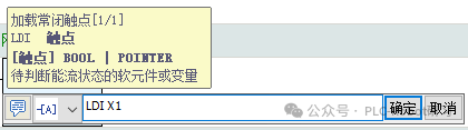
ILD—Load normally open immediate contact. This is only effective for the input point X of the PLC body, which distinguishes it from other brands of PLCs. It is used to immediately read the external input status of X at the current program execution point and update the contact status.
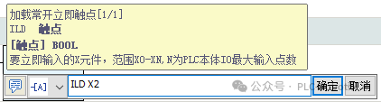
ILDI—Load normally closed immediate contact. The operand can only be the input point X of the PLC body, which is the opposite of the above instruction.
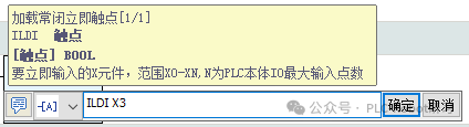
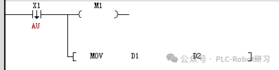
LDP—Take the rising edge of the pulse. The LDP instruction is used to capture the rising edge of the contact signal. If a rising transition of the corresponding signal is detected in this scan, the contact is valid; in the next scan, the contact becomes invalid.

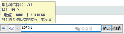
LDF—Take the falling edge of the pulse. If a falling transition of the corresponding signal is detected in this scan, the contact is valid; in the next scan, the contact becomes invalid.
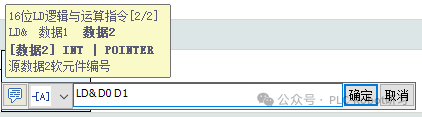
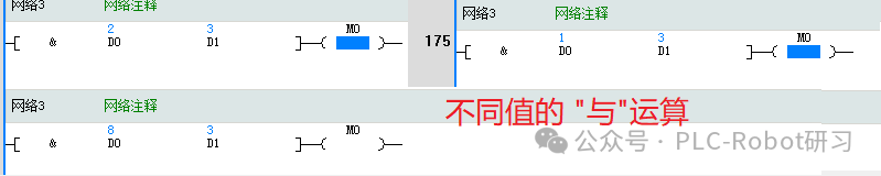
LD&—16-bit logical AND operation. The instruction input format is [LD& S1 S2]. The contents of [S1] and [S2] are logically operated (there are also “NOT” and “XOR” instructions). If the result is not 0, the instruction is conductive; if the comparison result is 0, the instruction is not conductive.
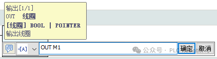
OUT—Output instruction. Drives the coil, does not support X elements.
LD#—Contact comparison instruction. Compares two operands and outputs the comparison result as a logical state. The two numbers involved in the comparison are treated as signed numbers.
Common contact comparison instructions include LD> greater than, LD= equal to, LD< less than, LD<> not equal to. If the operand is 32 bits, an additional D is added after the instruction, such as LDD> indicating 32-bit greater than.

MOV—16-bit transfer instruction. Copies data from the source data S to the target address. It requires contact drive and cannot be directly linked to the left bus. When 32-bit data processing is needed, the instruction changes to DMOV, at which point attention must be paid to address duplication issues.
When using 32-bit, the instruction:
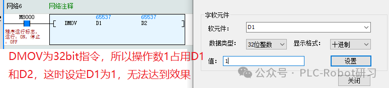
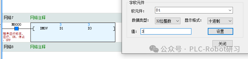
Therefore, when using DMOV, it is important to avoid address duplication. Modifying it as shown in the figure below will allow for normal data transmission.
The above are the most common input and output instructions when programming.