💥💥💞💞Welcome to this blog❤️❤️💥💥
🏆Author’s Advantage: 🌞🌞🌞The blog content aims to be logically clear and coherent for the convenience of readers.
⛳️Motto: A journey of a hundred miles begins with a single step.
💥1 Overview
The three-bar truss is a common structural form widely used in bridges, buildings, and mechanical equipment. The design optimization of the three-bar truss refers to adjusting parameters such as the size, shape, and connection methods of the bars to achieve the best performance and economy of the structure while meeting certain constraints.
The objective function and constraints of this paper are as follows:
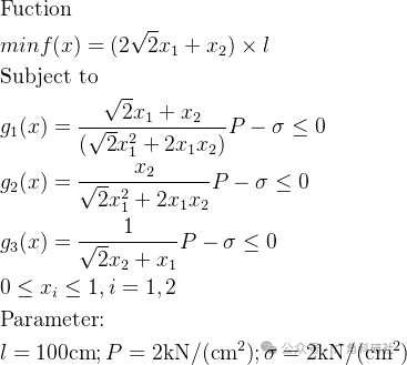

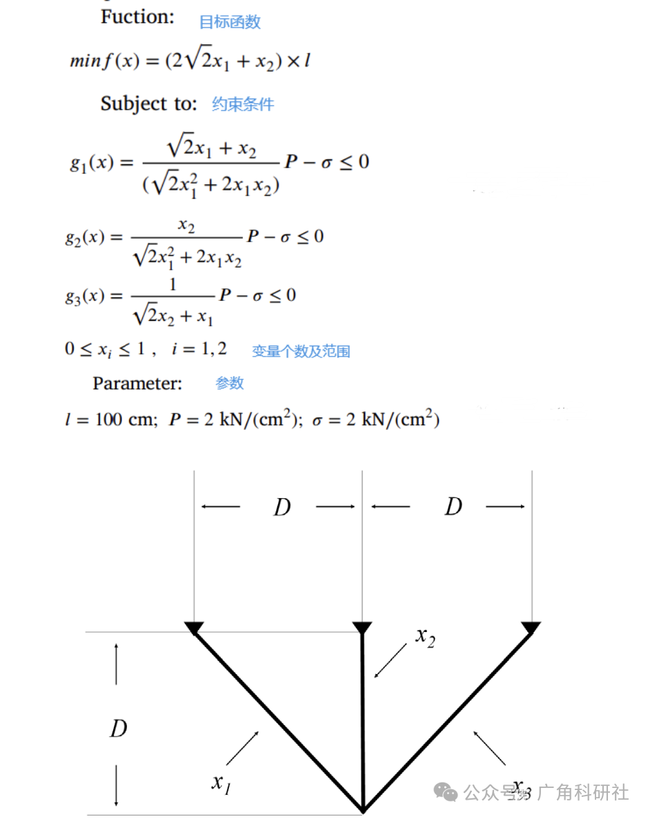

The main objectives of the three-bar truss design optimization include the following aspects:
-
Structural strength and stiffness: The design of the three-bar truss must meet certain strength and stiffness requirements to ensure that the structure does not become unstable or fail during use. Optimization can be achieved by adjusting parameters such as the cross-sectional area and length of the bars to provide the best strength and stiffness under external loads.
-
Structural weight: The weight of the three-bar truss directly affects the cost of the structure and the convenience of transportation and installation. Optimization can reduce the weight of the bars while ensuring that the strength and stiffness requirements are met.
-
Structural stability: The three-bar truss must remain stable under external loads to avoid instability and plastic deformation. Optimization can be achieved by adjusting the size and shape of the bars to provide the best stability under external loads.
-
Economic efficiency: The design of the three-bar truss must consider material costs, manufacturing costs, and maintenance costs to achieve the lowest total cost while meeting performance requirements.
To achieve the optimization of the three-bar truss design, researchers have employed various methods and techniques. These include traditional mathematical optimization methods such as linear programming, nonlinear programming, and integer programming, as well as modern optimization algorithms like genetic algorithms, particle swarm optimization, and simulated annealing. These methods and techniques can help researchers quickly search for optimal solutions during the design process, improving design efficiency.
Additionally, researchers have established numerical models and conducted simulation analyses to evaluate and optimize the performance of the three-bar truss. These models and analysis methods can help researchers better understand the behavior and response of the structure, guiding the optimization design process.
1. Basic Structure and Engineering Background of the Three-Bar Truss
The three-bar truss is a classic engineering structure formed by three bars connected by hinges to create a triangular frame, characterized by its simple structure and clear force distribution.
Basic Components:
Typically consists of three bars (labeled b1, b2, b3) connecting two or three nodes (such as nodes 1, 2, 3).
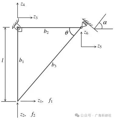

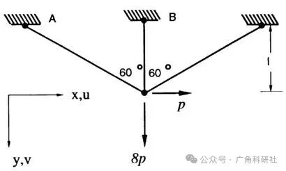

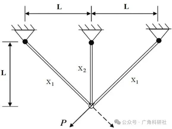

Nodes 1 and 3 are fixed to the horizontal plane, while node 2 bears external loads (such as vertical force PP or composite forces Fx, Fy).
Common configurations include equilateral triangles (with all bar lengths equal to LL) or asymmetric layouts.
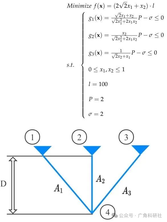

Application Scenarios:
Bridge supports, building roofs, and structures bearing complex loads in mechanical equipment.
The Pratt truss (with diagonal bars slanting inward) is suitable for medium spans, while the Howe truss (with diagonal bars slanting outward) is suitable for large spans.
Design Significance: The three-bar truss serves as a benchmark model in the field of structural optimization due to its hyperstatic characteristics and clear mechanical response, often used to validate the effectiveness of optimization algorithms.
2. Optimization Objectives and Design Criteria
The optimization objectives must enhance performance and economy while satisfying safety constraints, mainly including:
Weight Minimization:
This is the core objective, directly reducing material costs and the difficulty of transportation and installation.
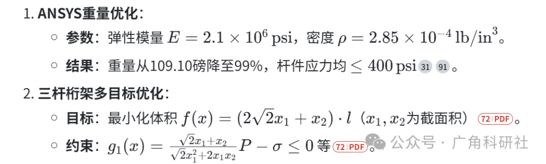
For example, an ANSYS optimization case reduced the initial weight of 109.10 pounds by 11%, with the objective function being minW=ρ∑AiLi (where Ai is the cross-sectional area and Li is the length of the bar).
Stiffness Maximization:
This is achieved by minimizing structural compliance, i.e., minc=∑wlUlTFl (where Ul is the displacement vector and Fl is the load vector).
Stability and Strength:
To avoid instability and plastic deformation, constraints on bar stress σi≤[σ] and node displacement uj≤[u] must be maintained.
Cost Control:
This involves balancing material prices and manufacturing processes, considering weight, cost, and displacement in multi-objective optimization.
Conflicts and Balance: Lightweight designs may compromise stiffness, necessitating multi-objective optimization or constraint coordination (e.g., stress limits of 400 MPa).
3. Mathematical Modeling and Optimization Methods
-
Finite Element Analysis (FEA)
Process:
Establish geometric model → Define material properties (E, ρ, ν) → Mesh generation → Apply loads and constraints → Solve for stress/displacement → Iterative optimization.
ANSYS Case:
Design variables: bar cross-sectional areas A1, A2, A3 and span B (with ranges Ai∈[1,1000] in², B∈[400,1000] in).
State variables: bar stress σi≤400 psi, objective function: minimize mass.
-
Topology Optimization
Truss-like continuum model:
Bar density αbj and direction are treated as design variables, allowing continuous variation through interpolation, avoiding the traditional “on/off element” jagged boundary problem.
Advantages: No intermediate density suppression, high numerical stability.
Feature Line Extraction:
Extract bar axes from topology results for easier engineering manufacturing.
-
Intelligent Optimization Algorithms
Algorithms
Optimization Results
Advantages
Source
CPOEBWO Minimum volume 263.24 cm³ (A1=0.7898 cm², A2=0.3985 cm²) Strong global optimization capability
Genetic Algorithm (GA) Discrete variable optimization, superior to traditional gradient methods Handles discrete variables, avoids local optima
Hybrid Algorithm (haDEPSO) Fast convergence speed, small standard deviation Combines advantages of differential evolution and particle swarm optimization
Algorithm Selection Trend: Integrating chaotic mapping (e.g., Fuch mapping) and adaptive weights (e.g., MAO algorithm) to enhance convergence accuracy.
4. Impact of Material Selection
Isotropic vs Anisotropic Materials:
Topology optimization essentially requires anisotropic materials (e.g., truss-like continuum), with composite materials like carbon fiber (CFRP) better matching theoretical models.
Thermal Deformation Control:
In spatial structures, CFRP’s low thermal expansion coefficient (e.g., M40 carbon fiber) significantly reduces thermal deformation and enhances dimensional stability.
Cost and Process:
Metal substrates (e.g., titanium alloys) are used for complex joints, balancing machining performance with carbon fiber compatibility requirements.
Multi-Material Optimization Case: Genetic algorithms simultaneously optimize bar materials and cross-sectional areas to achieve a Pareto front of weight-cost-displacement.
5. Constraints and Engineering Feasibility
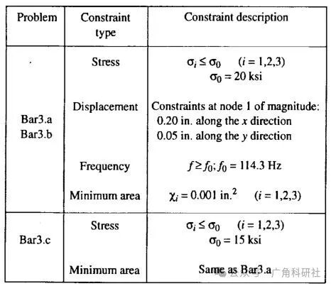
Constraints are core to ensuring structural safety, mainly including:
Stress Constraints:


Displacement Constraints:
Node displacement limits (e.g., total displacement ≤5 mm).
Geometric and Stability Constraints:
Avoid zero-bar removal leading to instability; collinear bars must be merged.
Fundamental frequency constraints (e.g., f≥114.3 Hz) to prevent resonance.

6. Case Studies

Truss-like Continuum Flexibility Optimization:
Method: Optimize bar distribution fields to generate non-orthogonal bar systems (Figure 1d).
Advantages: Captures detail features that traditional methods cannot achieve.
7. Future Research Directions
Multi-physical field coupling: Thermal-force joint optimization (e.g., space telescope trusses).
Deepening intelligent algorithms: Adaptive parameter adjustments, refining multi-objective Pareto fronts.
Integration of manufacturing constraints: Incorporating processing costs (e.g., welding costs) into optimization models.
Conclusion: The optimization of three-bar trusses requires a comprehensive approach integrating structural mechanics, materials science, and algorithm design. The research results can be extended to complex truss systems, promoting efficient and safe design of engineering structures.
📚2 Running Results
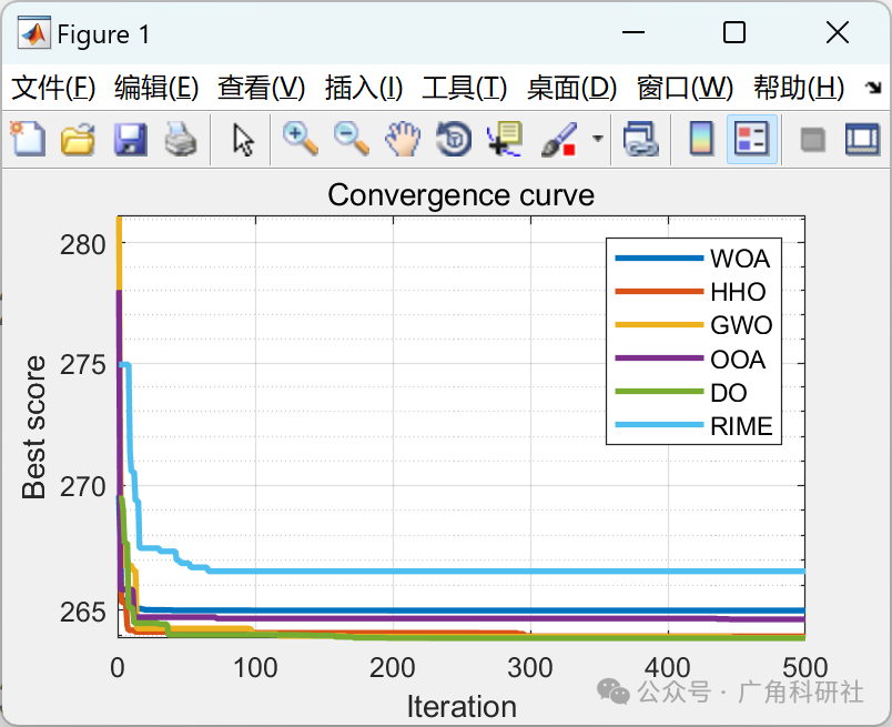

Partial Code:
function [lb,ub,dim,fobj] = Engineering_Problems(type)
% type: Problem type
% Different numbers correspond to different problems
% For example, type = 1: Select optimization Tension/compression spring design problem
% type = 2: Select optimization Pressure vessel design problem
switch type
case 1 % Tension/compression spring design problem
fobj = @spring; % Function
lb = [0.05 0.25 2]; % Lower limit
ub = [2 1.3 15]; % Upper limit
dim = length(lb); % Dimension
case 2 % Pressure vessel design problem
fobj = @ pvd;
lb =[0 0 10 10];
ub = [99 99 200 200];
dim = length(lb);
case 3 % Three-bar truss design problem
fobj = @ three_bar;
lb = [0 0];
ub = [1 1];
dim = length(lb);
end
function fitness = spring(x)
x1 = x(1);
x2 = x(2);
x3 = x(3);
f = (x3+2)*x2*(x1^2);
panaty_factor = 10e100; % Modify as needed
%
g1 = 1-((x2^3)*x3)/(71785*(x1^4));
g2 = (4*(x2^2)-x1*x2)/(12566*(x2*(x1^3)-(x1^4))) + 1/(5108*(x1^2))-1;
g3 = 1-(140.45*x1)/((x2^2)*x3);
g4 = ((x1+x2)/1.5)-1;
panaty_1 = panaty_factor*(max(0,g1))^2; % Penalty term for g1
panaty_2 = panaty_factor*(max(0,g2))^2; % Penalty term for g2
panaty_3 = panaty_factor*(max(0,g3))^2; % Penalty term for g3
panaty_4 = panaty_factor*(max(0,g4))^2; % Penalty term for g4
fitness = f + panaty_1+panaty_2+panaty_3+panaty_4;
end
function fitness = pvd(x)
x1= x(1);x2 = x(2);x3 = x(3);x4 = x(4);
f = 0.6224*x1*x3*x4 + 1.7781*x2*x3^2+3.1661*x1^2*x4+19.84*x1^2*x3;
panaty_factor = 10e100; % Modify as needed
%
g1 = -x1+0.0193*x3;
panalty_1 = panaty_factor*(max(0,g1))^2;
g2 = -x2+0.00954*x3;
panalty_2 = panaty_factor*(max(0,g2))^2;
g3 = -pi*x3^2*x4 – (4/3)*pi*x3^3 + 1296000;
panalty_3 = panaty_factor*(max(0,g3))^2;
g4 = x4 – 240;
panalty_4 = panaty_factor*(max(0,g4))^2;
fitness = f + panalty_1 + panalty_2 + panalty_3 + panalty_4;
end
function fitness = three_bar(x)
l = 100; P = 2; q = 2;
x1= x(1);
x2 = x(2);
f = l*(2*sqrt(2)*x1+x2);
panaty_factor = 10e100; % Modify as needed
%
g1 = P*(sqrt(2)*x1+x2)/(sqrt(2)*x1^2+2*x1*x2)-q;
penalty_g1 = panaty_factor*(max(0,g1))^2;
g2 = P*(x2)/(sqrt(2)*x1^2+2*x1*x2)-q;
penalty_g2 = panaty_factor*(max(0,g2))^2;
g3 = P/(sqrt(2)*x2+x1)-q;
penalty_g3 = panaty_factor*(max(0,g3))^2;
fitness = f+penalty_g1+penalty_g2+penalty_g3;
end
end
🎉3 References
Some content in this article is sourced from the internet, and references will be noted. If there are any inaccuracies, please feel free to contact for removal.
[1] Ye Youdong, Wang Ya. Optimization Design of Three-Bar Truss Based on ANSYS Analysis [J]. Coal Mine Electromechanics, 2004(5):5. DOI:10.3969/j.issn.1001-0874.2004.05.039.
[2] Zhu Qin, Yang Haixia. Truss Structure Optimization Design Based on Particle Swarm-Cuckoo Search Algorithm [J]. Journal of Three Gorges University (Natural Science Edition), 2017(1). DOI:10.13393/j.cnki.issn.1672-948X.2017.01.014.
🌈4 Matlab Code Implementation