This article provides an in-depth introduction to the architecture of the Low Energy Bluetooth (BLE) protocol stack and explores how to leverage existing BLE applications to fully realize the potential of low-power wireless communication. This knowledge is essential for efficiently and reliably conducting design, troubleshooting, and optimizing applications.IntroductionLow Energy Bluetooth (BLE) is a key technology in the Internet of Things (IoT) ecosystem. Originally developed as a wireless protocol to replace cables in consumer electronics products such as keyboards, mice, and headsets, its functionality has significantly expanded over time, no longer serving merely as a cable replacement. Today, it plays a vital role in various industries such as healthcare, retail, and automotive, as well as in industrial applications like location tagging and instrument control.According to the “2023 Bluetooth Market Update,” the compound annual growth rate (CAGR) of device shipments supporting Bluetooth wireless technology is 9% from 2023 to 2027. It is expected that by 2027, the shipment of BLE devices will more than double, with 97% of all Bluetooth-enabled devices adopting BLE.BLE is a wireless technology that was introduced with the Bluetooth 4.0 specification in July 2010. Previously known as Bluetooth Smart, it is designed for ultra-low power devices.Traditional Bluetooth technology, which we are familiar with, is primarily used for pairing smartphones with headsets and transferring large amounts of data such as music and photos. In contrast, BLE is optimized for applications that do not require large data transfers, making it an ideal choice for various power-sensitive applications. Traditional Bluetooth remains active and consumes power even when not in use, while BLE stays in sleep mode most of the time, waking only when a connection is established, and the connection duration typically lasts only a few milliseconds. This efficient power management, combined with data rates of up to 1 Mbps (reaching 2 Mbps in BLE 5.0), allows BLE devices to operate with extremely low power consumption.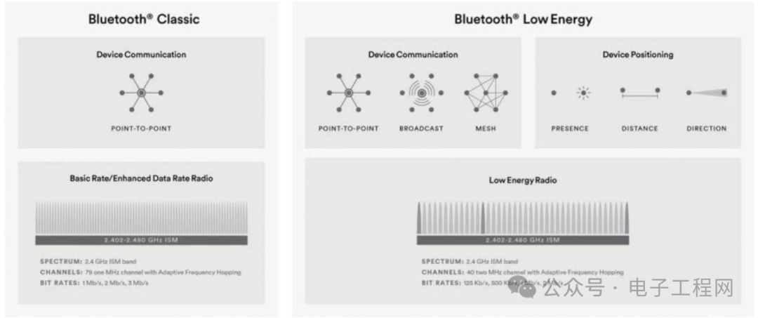 Figure 1. (a) Classic Bluetooth and (b) Low Energy Bluetooth Specifications Overview
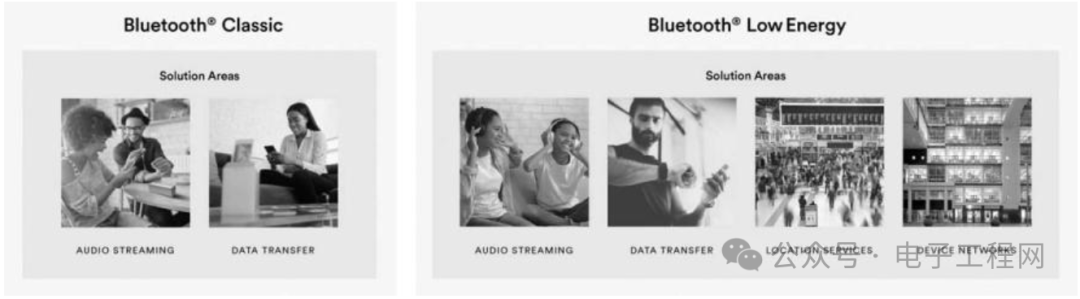 Figure 2. (a) Classic Bluetooth and (b) Low Energy Bluetooth ApplicationsBluetooth SpecificationsAs shown in Figures 1 and 2:► Classic Bluetooth: Represents the earliest version of Bluetooth, with higher data rate capabilities suitable for streaming, high-bandwidth file transfers, and headsets. It has 79 RF channels, of which 32 are broadcast channels for other devices to discover and connect.► Low Energy Bluetooth: Designed for low-power applications with infrequent data transmission, such as sensors and other low-bandwidth transmissions. It has 40 RF channels, of which 3 channels are used for device discovery.Overview of BLE ApplicationsA typical BLE application consists of two devices: a peripheral device and a central device. Before establishing a connection, the peripheral device announces its presence through a process called BLE advertising. The central device scans for available peripheral devices. Once the central device finds the desired peripheral device, a connection is established between the two. Each device’s application can then transmit data through different layers of the BLE protocol stack, enabling mutual communication. See Figure 3.For example, a smartphone can act as the central device, while a fitness tracker can serve as the peripheral device. The fitness tracker, acting as a server, collects data such as heart rate, blood pressure, ECG, step count, and even sleep patterns. The fitness tracker broadcasts its presence to nearby devices, including the smartphone acting as a client. The smartphone retrieves this data from the fitness tracker and displays it in a user-friendly application. This is just one example of the many applications supported by BLE, which we will discuss further in the latter part of the article.
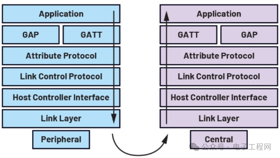 Figure 3. Layers of Peripheral and Central DevicesBLE Protocol Stack ArchitectureThe BLE protocol stack architecture (as shown in Figure 4) is a structured software framework that enables communication between BLE devices. It defines the necessary layers and protocols for establishing, maintaining, and terminating Bluetooth connections, facilitating data exchange between devices.The BLE protocol stack architecture is typically divided into three main layers: the application layer, the host layer, and the controller layer. The application layer is the topmost layer of the protocol stack. Applications running on BLE devices utilize and process actual data at this layer. The host layer sits between the application layer and the controller layer in the protocol stack, implementing all the higher-level protocols and profiles required for BLE communication. Additionally, it provides high-level application programming interfaces (APIs) that allow applications to interact with the lower layers of the protocol stack. The controller layer is the hardware part of the BLE protocol stack, responsible for sending and receiving Bluetooth signals. The controller layer handles tasks such as frequency hopping, modulation, and demodulation. These layers work together to achieve efficient and reliable communication between BLE devices.
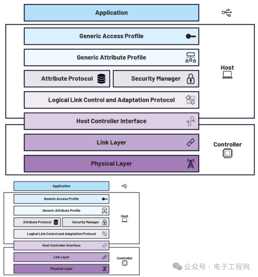 Figure 4. BLE Protocol Stack ArchitectureApplicationThe application layer is used to implement specific application requirements for BLE devices. The application layer interacts with the lower layers of the protocol stack through GATT (Generic Attribute Profile), based on services, characteristics, and corresponding data defined by GATT.The characteristics and behaviors of devices are designed at the application layer. This includes defining services and characteristics, specifying data exchange methods, and implementing event handling logic for connection, disconnection, data updates, etc. The main role of the application layer is to customize the BLE protocol stack according to the specific needs of the device and its intended use case.HostThe host layer contains the remaining upper-layer protocols of the BLE protocol stack, specifically including the Logical Link Control and Adaptation Protocol (L2CAP), Security Manager Protocol (SMP), Attribute Protocol (ATT), Generic Attribute Profile (GATT), and Generic Access Profile (GAP). L2CAP serves as a channel interface between upper and lower layer protocols, responsible for segmenting and encapsulating application data and transmitting data packets using ACL links. L2CAP correctly locates endpoints on devices using channel identifiers (CIDs) and channel multiplexing. See Figure 5.
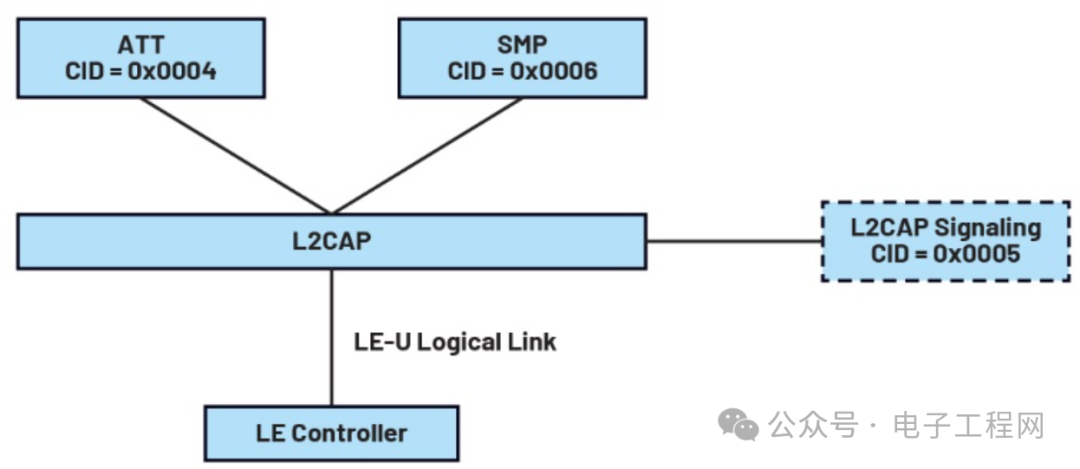 Figure 5. L2CAP Data PacketL2CAP SignalsIn the BLE protocol stack, commands are exchanged between devices in the form of requests and responses. Here are some key points regarding commands:► Commands are sent in the form of requests and responses.► Each Protocol Data Unit (PDU) can send one command.► PDUs containing L2CAP signaling messages are called C frames (Control Frames), while data frames are divided into B frames (Basic Information Frames) and LE frames (Low Energy Information Frames). See Figure 6.
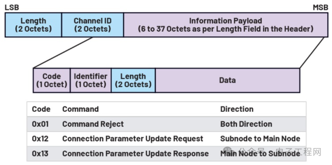 Figure 6. L2CAP Frame Format► Command Reject (Command Rejected)■ Response sent when the command code is unrecognized or the command length is incorrect■ Possible reasons■ Unknown command■ Exceeds LCAP signaling maximum transmission unit (MTU)■ Invalid CID in the request► Connection Parameter Update Request■ Sent by the LE node to the LE master node, requesting a new set of connection parameters■ Connection parameters■ Interval min■ Interval max■ Node latency■ Timeout multiplier► Connection Parameter Update Response■ Sent by the LE master node to the LE node in response to the connection parameter update requestSMP defines the pairing, authentication, and encryption procedures between BLE devices. SMP commands execute these procedures using L2CAP services. SMP command packets consist of a code field and a data field. The code field identifies the type of command, while the length and format of the data field depend on the command type. All SMP procedures implement a 30-second timeout to determine if the procedure has failed. See Table 1.Table 1. SMP Command Codes
| Code | Description | Phase |
| 0x00 | Reserved | — |
| 0x01 | Pairing Request | Phase 1 |
| 0x02 | Pairing Response | Phase 1 |
| 0x03 | Pairing Confirm | Phase 2 |
| 0x04 | Random Pairing | Phase 2 |
| 0x05 | Pairing Failed | Phase 2 |
| 0x06 | Encryption Information | Phase 3 |
| 0x07 | Master Identification | Phase 3 |
| 0x08 | Identification Information | Phase 3 |
| 0x09 | Identity Address Information | Phase 3 |
| 0x0A | Signature Information | Phase 3 |
| 0x0B | Security Request | Phase 1 |
| 0x0C to 0x0FF | Reserved | — |
ATT defines the rules for accessing device attributes or data. It supports discovering, reading, and writing attributes on remote devices. ATT follows a client-server model. The server exposes a set of attributes, while the client can discover, read, and write these attributes. The attribute structure in ATT consists of a handle, type, value, and permissions. The attribute handle is a unique non-zero identifier assigned to each attribute on the server. The attribute type specifies the meaning of the attribute through a universally unique identifier (UUID). UUIDs can be either 16-bit UUIDs assigned by the Bluetooth Special Interest Group (SIG) or custom 128-bit UUIDs. The attribute value is the actual data value of the attribute, while the attribute permissions determine the level of access allowed for the attribute. See Figure 7. Figure 7. Attribute StructureATT defines six types of Protocol Data Units (PDUs): request, response, command, confirmation, notification, and indication (Figure 8). Request PDUs are sent from the client to the server to request a reply. Response PDUs are the server’s reply to the client when responding to a request. Command PDUs are sent from the client to the server without requiring a reply. Indication PDUs are sent from the server to the client and require a reply. Confirmation PDUs are sent from the client to the server as a reply to an indication. Notification PDUs are sent from the server to the client without requiring a reply. Through these PDU types, clients and servers can exchange information and control at the ATT layer of the BLE protocol stack.
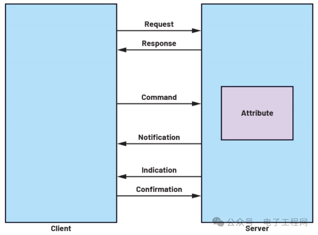 Figure 8. Different Types of Attribute PDUsATT PDU packets consist of an opcode, attribute parameters, and an authentication signature (Figure 9). The opcode field is used to identify the method/type of the PDU, such as request or response. It also includes a command flag to indicate whether the PDU type is a command, and an authentication signature flag to indicate whether the packet uses an authentication signature.
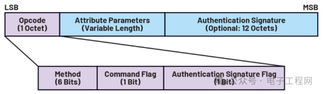 Figure 9. ATT PDU Packet Format
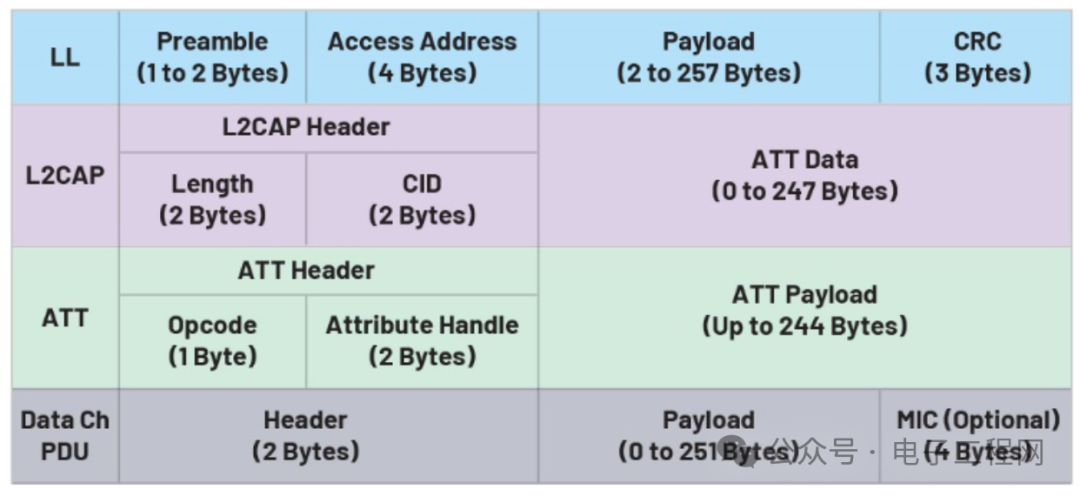 Figure 10. BLE Layer Data Packet FormatFigure 10 summarizes the data packet formats at each layer of the BLE protocol stack and provides an overview of the data structure.Moving up from the host layer, the next higher layer is GATT. The Generic Attribute Profile (GATT) is responsible for defining the formatting, encapsulation, and interaction rules for data or attributes between devices. GATT procedures include attribute discovery, reading, writing, notifications, and indications. It provides a standard framework for managing data within BLE devices.A BLE device may have multiple GATT profiles (Figure 11). The Bluetooth specification defines standard profiles to ensure interoperability between BLE devices produced by different manufacturers. However, custom profiles can also be implemented based on specific application requirements. Therefore, understanding the structure of GATT profiles is crucial.GATT profiles consist of services. A service refers to a set of related attributes defined in the ATT protocol. In GATT, the term “characteristic” is often used to refer to attributes, but characteristics may also contain descriptors that are attributes themselves. Characteristics serve as containers for user data, while descriptors provide descriptions or additional information about the user data.
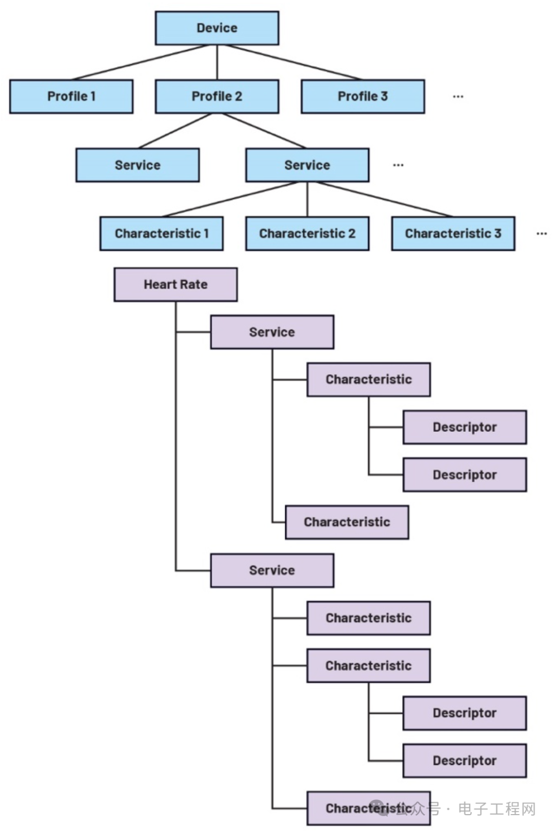 Figure 11. GATT Profile StructureSimilar to ATT, GATT also has two roles: GATT client and GATT server. The GATT client is the device that accesses data on the remote GATT server. The GATT server is the device that supports remote GATT clients in accessing data. In GATT, a device’s role is determined by the direction of data access.At the host layer of the BLE protocol stack, the Generic Access Profile (GAP) is the top-level protocol that defines how Bluetooth devices access and communicate with each other. GAP covers device operating modes, discovery processes, connection establishment, and security mechanisms. All Bluetooth-enabled devices must implement GAP, as it provides a standard framework for controlling BLE devices.GAP provides different roles for BLE devices based on their activity status. When a connection is not needed, a BLE device can act as either a broadcaster or an observer. A broadcaster is a device that announces its presence within a nearby range. It primarily uses the broadcaster role of the link layer to send broadcasts. An observer, in contrast, uses the scanner role of the link layer to scan the relevant area to receive broadcasts from nearby devices. In real life, examples of broadcasters include BLE beacons, while examples of observers include BLE hubs that collect data. See Figure 12.
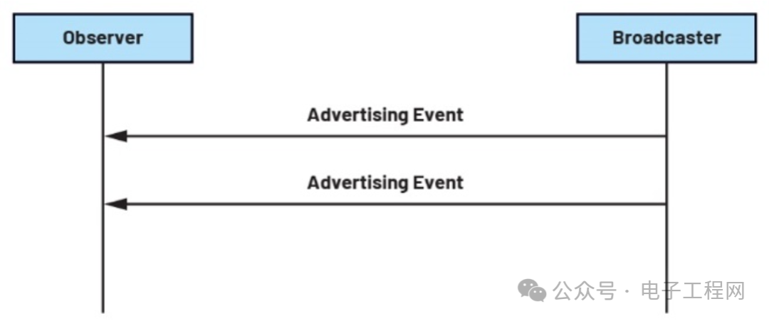 Figure 12. Broadcaster Sending Broadcast Data Packets to ObserverWhen a connection can be established, GAP provides two additional roles for BLE devices: peripheral and central devices. Peripheral devices, similar to broadcasters, announce their presence and wait for connection requests from remote central devices. Central devices act as observers, scanning for peripheral devices and initiating connection requests to the desired peripheral devices. As mentioned earlier, examples of peripheral devices include smartwatches, fitness trackers, and home automation sensors, while examples of central devices include smartphones, tablets, and laptops. See Figure 13.
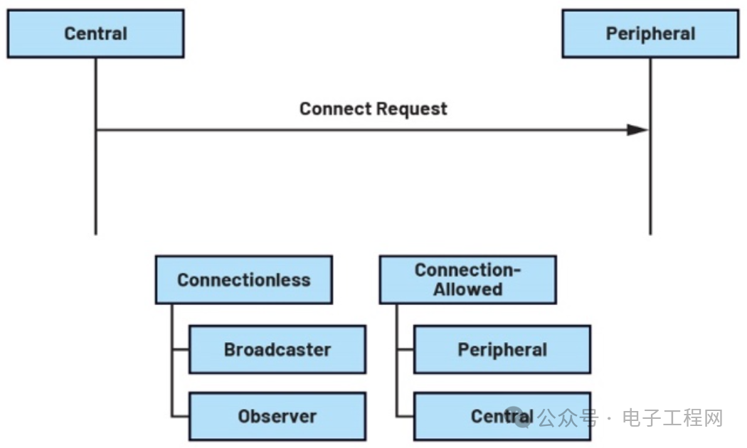 Figure 13. Central Device/Peripheral Device vs Broadcaster/ObserverAccording to the requirements of the Bluetooth specification, the GAP service must be implemented by the GATT server within a profile. The GAP service covers various characteristics related to basic device information, typically including: device name, device appearance, preferred connection parameters for peripheral devices, central device address resolution, and private addresses that can only be obtained through resolution.ControllerThe controller consists of two layers: the link layer and the physical layer. The physical layer is at the bottom of the BLE protocol stack and is responsible for the actual transmission and reception of wireless signals. The physical layer operates in the 2.4 GHz ISM band and uses Gaussian Frequency Shift Keying (GFSK) modulation scheme. This modulation scheme achieves efficient data transmission by changing the frequency of the carrier signal.The physical layer consists of 40 channels, each spaced 2 MHz apart:► 3 broadcast channels are used to broadcast short data packets to announce the broadcaster’s presence and its available services or information.► 37 data channels are used after a connection is established between the central device and the peripheral device.Before the release of the Bluetooth 5 core specification, BLE only used 3 fixed broadcast channels (37, 38, 39). The extended advertising feature introduced by Bluetooth 5 allows the 37 data channels originally used for data transmission to be used as auxiliary broadcast channels. This extension unlocks new features in Bluetooth 5 and expands the physical layer’s coding scheme options. See Figure 14.
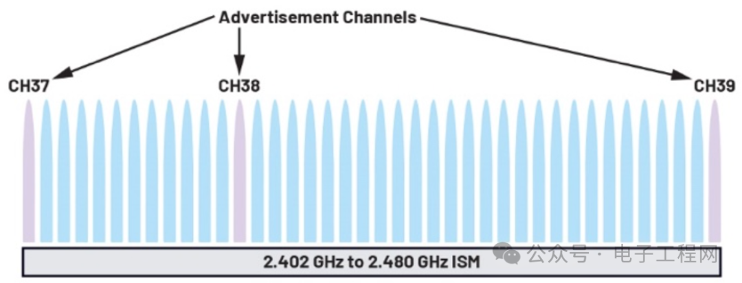 Figure 14. BLE ChannelsBluetooth 5 introduces three different types of physical layer (PHY) types, supporting three modulation schemes and four data transmission rates (Table 2). The default physical layer (PHY) is LE 1M, operating at a modulation scheme of 1 megasymbols per second (1 Msym/s), achieving a data transmission rate of 1 megabit per second (1 Mbps) with a wireless transmission range of up to 100 meters. Another type of physical layer (PHY) is LE 2M, which uses a 2 Msym/s modulation scheme, increasing the data transmission rate to 2 Mbps. The third physical layer (PHY) is LE Coded, supporting data transmission rates of 125 Kbps and 500 Kbps. Similar to the LE 1M mode, LE Coded uses a 1 Msym/s symbol rate modulation scheme. In the 125 Kbps data rate encoding, each bit of data is expanded to 8 symbols (S=8), while in the 500 Kbps data rate encoding, each bit of data is expanded to 2 symbols (S=2). This coding scheme makes LE Coded PHY suitable for long-range applications, achieving transmission distances of up to 1000 meters in open space (supporting forward error correction to reduce the error rate). Table 2. Different PHYs in BLE
| Modulation |
Coding Scheme |
|||
| PHY | Scheme | Access Header | Payload | Data Rate |
| LE 1M | 1 Msymps Modulation | Uncoded | Uncoded | 1 Mbps |
| LE 2M | 2 Msymps Modulation | Uncoded | Uncoded | 2 Mbps |
| LE Coded | 125 Kbps | S = 8 | S = 8 | 125 kbps |
| Response | S = 2 | 500 kbps |
► The layer above the physical layer (PHY) is the link layer, which is responsible for managing scanning, broadcasting, connection establishment, and link maintenance between devices. The link layer also manages the channel selection for data transmission, using adaptive frequency hopping spread spectrum to reduce interference. The link layer state machine defines five states: ready state, broadcasting state, scanning state, initiating state, and connected state (see Figure 15).► When idle, the link layer is in the ready state, not transmitting or receiving data packets.► In the broadcasting state, the link layer (acting as a broadcaster) sends broadcast data packets while listening for devices requesting additional information.► In the scanning state, the link layer (acting as a scanner) listens to broadcasters and can actively send scan requests to obtain more additional information.► In the initiating state, the link layer (acting as an initiator) listens for data packets from broadcasters and responds to broadcast packets, initiating a connection request to the broadcaster.► When the link layer connects to another BLE device’s link layer, it is in the connected state.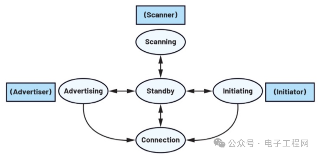 Figure 15. Link Layer State TransitionIn addition to different states, the link layer also defines the following events: broadcast events and connection events. Broadcast events involve transmitting data packets using broadcast channels, while connection events involve transmitting data packets in a connected state through data channels.The link layer also defines the format of BLE data packets transmitted by the physical layer. The packet format is divided into coded PHY (Coded PHY) and uncoded PHY (Uncoded PHY).
 Figure 16. Uncoded PHY BLE Data PacketAs shown in Figure 16, an uncoded PHY BLE data packet starts with a preamble, followed by an access address, PDU, and cyclic redundancy check (CRC).As shown in Figure 17, a coded PHY BLE data packet consists of a preamble, forward error correction (FEC) block 1, and FEC block 2.► The preamble is an alternating sequence of 1s and 0s used for frequency synchronization. For LE 1M, its length is 1 byte; for LE 2M, its length is 2 bytes.► The access address serves as an association code for devices tuned to the physical channel; its length is 4 bytes. For the physical broadcast channel, the access address is a fixed value of 0x8E89BED6.► The PDU contains the payload from the upper layers of the BLE protocol stack. It can be a broadcast PDU or a data PDU, which may contain important information needed for communication from sensors or other devices. More information will be discussed in the next section.► The CRC is used for error checking.
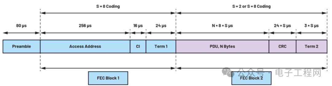 Figure 17. Coded PHY BLE Data Packet► Constant Tone Extension (CTE) consists of a sequence of continuously modulated non-whitened 1s, which is typically used selectively. CTE is crucial for the direction-finding capabilities of BLE.► FEC block 1 contains the access address, coding indicator (CI), and block terminator (TERM1). CI indicates the coding scheme used by FEC block 2, while TERM1 is a 3-bit block terminator.► FEC block 2 contains the PDU, CRC, and TERM2, with the coding scheme being the same as indicated by the CI field in FEC block 1.Whether using uncoded PHY or coded PHY, the BLE data packet PDUs can be divided into two categories: broadcast channel PDUs and data channel PDUs. See Figures 18 to 21.
 Figure 18. Broadcast Physical Channel PDU
 Figure 19. Broadcast Physical Channel PDU HeaderAs shown in Figure 19, the broadcast channel PDU is used for broadcast events. It consists of a 2-byte header and a payload of up to 255 bytes.The header contains the following fields: PDU type, RFU (reserved for future use) bits, ChSel, TxAdd, RxAdd, and length. The values of ChSel, TxAdd, and RxAdd bits depend on the PDU type, while the length field describes the length of the payload (in bytes).
 Figure 20. Data Physical Channel PDU
 Figure 21. Data Physical Channel PDU HeaderAs shown in the above figures, the data channel PDU is used for connection events. It consists of a 2 or 3-byte header, a payload, and a message integrity check (MIC) for encrypting the link.The data channel PDU header contains the following fields: LLID, NESN, SN, MD, CP, length, and CTEInfo.► LLID is used to describe the type of link layer data PDU.► NESN (Next Expected Sequence Number) is used to identify the next data packet expected to be sent by the peer device.► SN (Sequence Number) is used to identify the current data packet.► CP (CTEInfo present) indicates the presence of an additional CTEInfo field.► The length field describes the length of the payload (in bytes).► CTEInfo describes the type and length of the CTE.Host Controller Interface (HCI)HCI acts as an intermediary between the host and the controller. It provides a set of standardized commands and events to support communication between these two layers.HCI supports various types of transport layers, including UART, USB, SDIO, and three-wire UART. Each transport layer has its own specifications and requirements. This overview focuses on the UART transport layer.According to the Bluetooth 5.2 specification, the UART transport layer supports five types of packets: command, event, asynchronous connectionless (ACL) data, synchronous (SCO) data, and isochronous (ISO) data.► The host uses command packets to send commands to the controller. These commands instruct the controller to perform specific operations or configurations.► The controller uses event packets to inform the host of events that have occurred. Events can include changes in connection status, data reception, or other relevant information.► ACL packets are used for exchanging data between the host and the controller. They support the transmission of asynchronous data, such as information from sensors or user input.► SCO packets are used for exchanging synchronous data between the host and the controller. However, it is important to note that BLE does not support SCO packets, as SCO packets are primarily used for voice or audio transmission in classic Bluetooth.► ISO packets are a new type of packet that supports the transmission of time-sensitive data between devices using BLE. Isochronous packets are designed for applications requiring precise timing, such as audio streaming or real-time control.
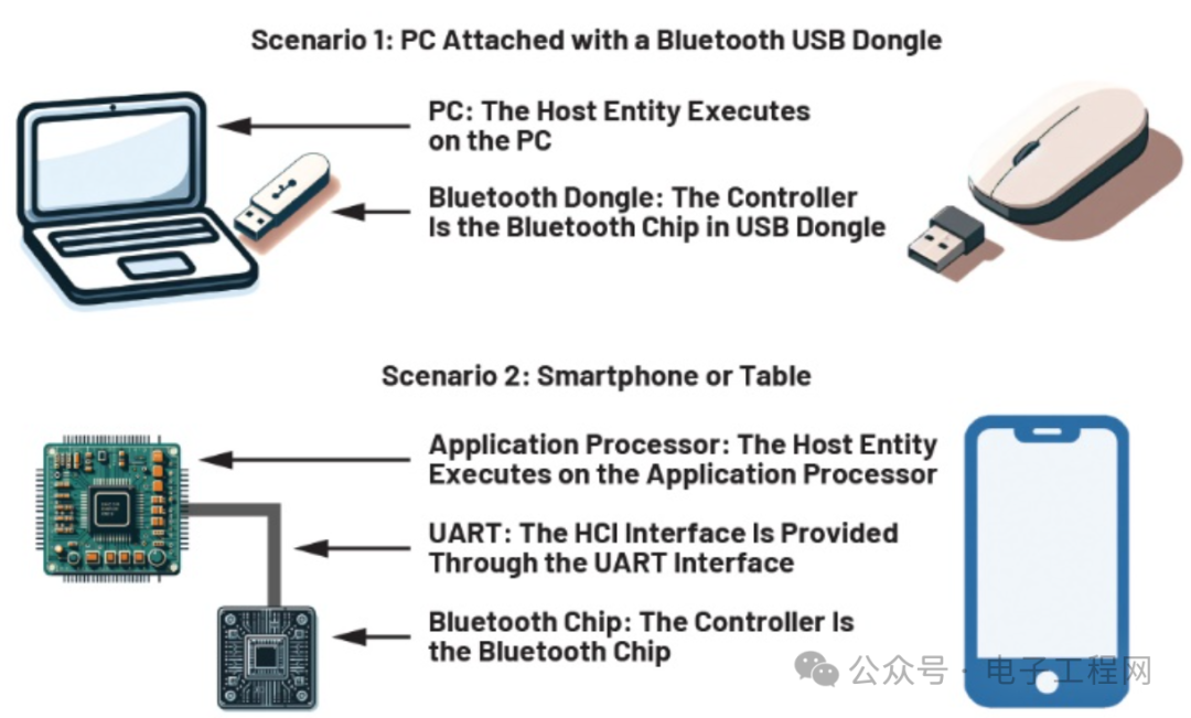 Figure 22. Bluetooth ApplicationsWhy Is It Important?BLE is widely used in various scenarios, from consumer products to industrial environments, making it beneficial to understand BLE and its significance. BLE is a continuously evolving and upgrading protocol that offers endless possibilities for application development.Use CasesBLE is widely applied across numerous industries, subtly influencing our daily lives (Figure 22). Familiarity with BLE helps individuals understand and leverage its advantages in various application scenarios. BLE has made significant contributions to many fields, driving innovation in existing processes. Here are some of those fields:BLE Applications in HealthcareBLE plays a crucial role in healthcare. BLE technology enables devices such as blood glucose meters and blood pressure monitors to function, and even implantable devices like pacemakers that require ultra-low power can perform better. These devices can collect data and transmit real-time reports to patients and healthcare institutions. BLE can also be used for patient tracking, locating room or floor numbers, and transmitting information to medical responders.BLE Applications in Location TrackingWith BLE technology, advanced trackers or smart tags can be attached to bags, keys, or even pets to track their locations. These tags are designed to be very small and energy-efficient, making BLE’s low power characteristics essential. Many industries are also utilizing BLE technology, such as warehouse inventory monitoring, grocery store management, and indoor navigation.BLE Applications in Wearable DevicesWearable devices require lightweight and long-lasting battery life, making BLE technology an ideal choice. Smartwatches, fitness bands, and smart glasses commonly use BLE for wireless connectivity and reduced power consumption.BLE Applications in Audio StreamingBLE plays an important role in audio streaming applications. With the introduction of LE Audio, BLE now supports low-latency audio streaming, providing a better audio experience. LE Audio uses Low Complexity Communication Codec (LC3), which ensures audio quality is maintained at low data rates. This opens up new possibilities for wireless audio consumption.BLE Applications in Home AutomationIn the field of home automation, BLE is the foundational technology for smart homes. The Internet of Things is widely applied in smart homes, and BLE supports seamless connectivity between various smart devices. There are various smart devices available in the market that support BLE for home automation, such as key fobs, home beacons, and switches. BLE allows users to control and monitor various aspects of their homes, such as smart lighting, efficient energy management, smart locks, wireless speaker systems, home robots, and security systems.ConclusionIn the BLE protocol stack, application data must undergo multi-layer protocol processing to reach the remote application of another device (which also has its own BLE protocol stack). The complete process is as follows:1. Application Layer: The application program selects the appropriate attributes to store the data to be transmitted.2. ATT Layer: Generates ATT layer packets containing information corresponding to the target attributes of the remote device.3. L2CAP Layer: The packets from the ATT layer are processed by the L2CAP layer. If necessary, L2CAP performs data segmentation and reassembly. This layer adds L2CAP headers to each L2CAP packet.4. Link Layer: The L2CAP packets are passed to the link layer, which forwards the packets to the physical layer for wireless transmission. The link layer adds link layer headers to the packets, forming Protocol Data Units (PDUs).5. Physical Layer: Before transmission, the physical layer adds the necessary preamble, access address, and CRC to the PDUs. The packets are then transmitted wirelessly.At the receiving end, the remote BLE device receives the packets and executes the reverse process to extract the data.When implementing BLE in different applications, selecting the appropriate hardware is key to achieving optimal efficiency and optimization. For various requirements and applications, ADI offers a range of microcontrollers that support BLE.The MAX32665/MAX32666/MAX32667/MAX32668 DARWIN series low-power microcontrollers are designed for a wide range of practical applications. These MCUs support Bluetooth 5 low-power radio connections, allowing wireless connections with multiple devices for IoT applications while maintaining the lowest possible active power and standby power. The DARWIN MCUs also feature the largest embedded memory in their class, supporting larger-scale applications and more protocol stacks. This flexibility and capability provide endless possibilities for design and addressing various challenges in the IoT space, solidifying the foundation of modern IoT solutions and paving the way for future developments.
Follow 【Electronic Engineering Network】 for more information on the electronics industry.