Click the blue "Arm Selected" at the top left and select "Set as Star"1. Background
With the development of the times and the advancement of technology, the trend for security needs has become increasingly evident. ARM has been continuously adjusting and updating its new architectures, many of which are related to security. Below are some architectures related to security.
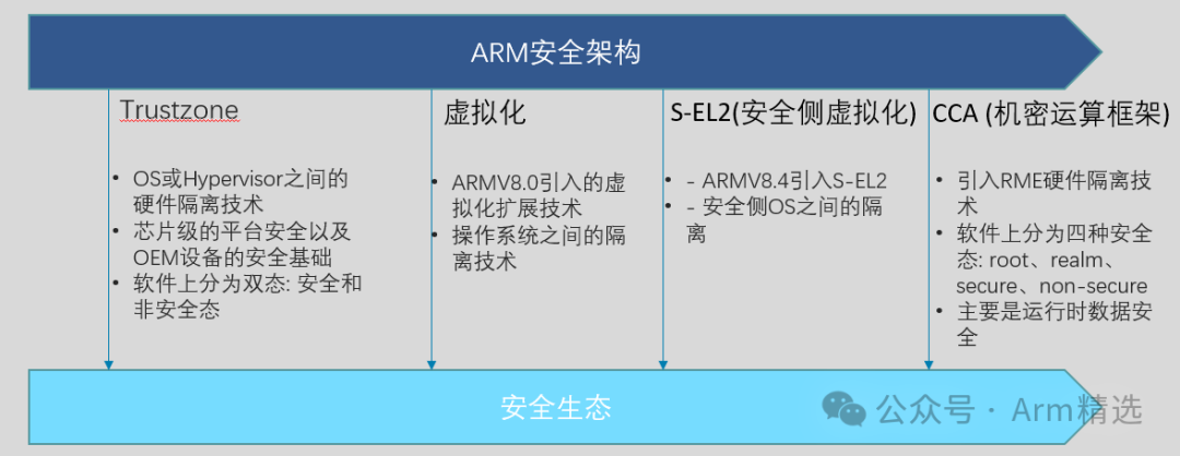
As part of ARM’s security architecture, TrustZone technology was first released by ARM in December 2008. In 2013, Apple launched the first iPhone with fingerprint unlocking: the iPhone 5s, which ensured the security of fingerprint information through the Secure Enclave technology that was deeply customized based on the ARM TrustZone architecture. This was probably the first time TrustZone technology came into the public eye. Today, TrustZone technology has become an important foundational technology in the field of mobile security. You may not be familiar with its technical principles, but it has been quietly protecting your fingerprint information, account passwords, and various sensitive data. Below is a block diagram of a fingerprint under the TrustZone architecture, which has been quite popular in recent years (2015-present).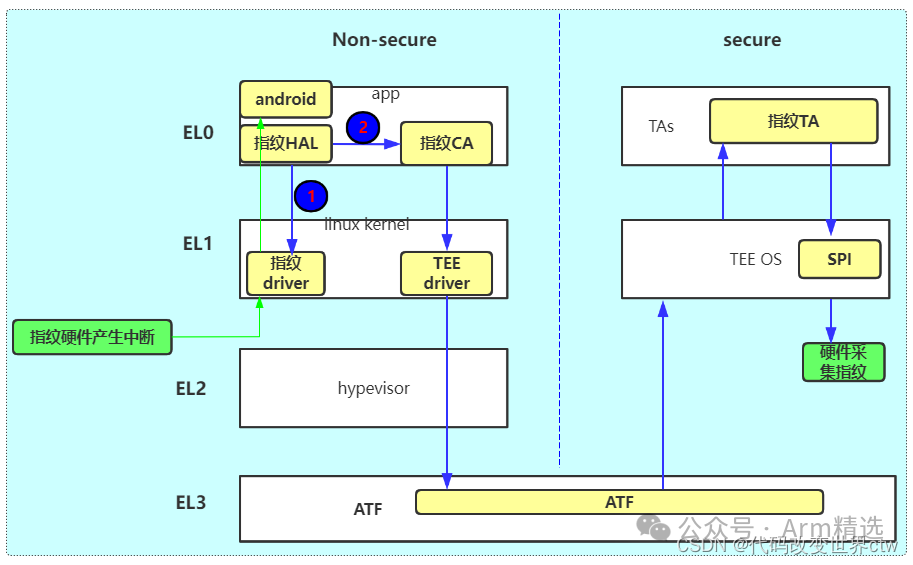
2. What is TrustZone?
So what exactly is TrustZone? ARM TrustZone does not specifically refer to a piece of hardware or software, but rather a technical architecture. Initially, TrustZone was just the name of the security architecture within the Arm A-profile architecture. TrustZone was first introduced in Armv6K, and Armv7-A and Armv8-A also support TrustZone. TrustZone provides two execution environments that are hardware-isolated across the system, as shown in the figure below: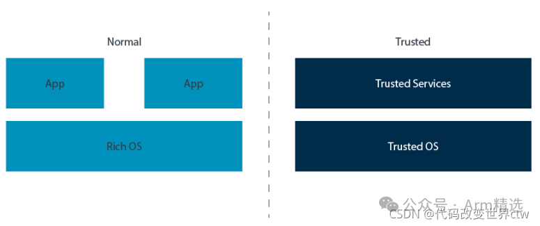 The normal world runs a rich set of software. This software stack typically includes a large application suite, a complex operating system (like Linux), and possibly a hypervisor program. Such software is large and complex. Although efforts can be made to protect them, the size of the attack surface means they are more susceptible to attacks. The trusted world runs a smaller, simpler software known as the Trusted Execution Environment (TEE). Typically, a TEE includes multiple trusted services hosted by a lightweight kernel. The attack surface of this software is much smaller, which helps reduce vulnerabilities to attacks.
You may sometimes see the term Rich Execution Environment (REE) used to describe software running in the normal world.
TrustZone aims to strike a balance. As users and developers, we want the rich functionality and flexibility of the Normal world while also wanting to use smaller, more restricted software in the Trusted world to achieve a higher degree of trust. TrustZone provides us with both, offering hardware-enforced isolation between the two environments.
TrustZone for Armv8-MTrustZone is also used to refer to the security extensions in the Armv8-M architecture. While there are similarities between TrustZone in the A-profile architecture and the M-profile architecture, there are also significant differences. This article primarily focuses on the A series.
3. TrustZone Technology in Processors
Next, we will discuss processor support for TrustZone.
3.1. Two Security States: Secure and Non-Secure
In the Arm architecture, there are two security states: secure and non-secure.
At EL0, EL1, and EL2 levels, the processor can be in a secure or non-secure state, controlled by the SCR_EL3.NS bit. Therefore, you often see it written like this:
-
NS.EL1: Non-secure state, Exception level 1
-
S.EL1: Secure state, Exception level 1
Note: Regardless of the value of the SCR_EL3.NS bit, EL3 is always in a secure state. The arrangement of secure states and exception levels is shown below: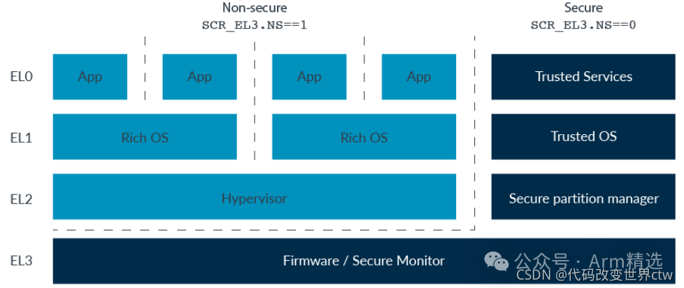
3.2. Switching Security States
If the processor is in NS.EL1 and the software wants to move to S.EL1, how is this done? To change the security state in either direction, execution must go through EL3, as shown in the figure below: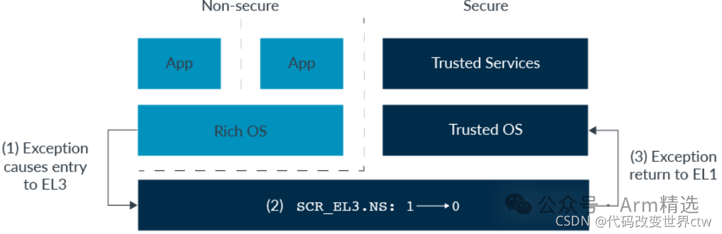 The figure above shows an example sequence of steps involved in moving between secure states. These steps are taken at once:
-
Entering a higher exception level requires an exception. Typically, this exception is a FIQ or SMC (Secure Monitor Call) exception. We will later look at interrupt handling and SMC in more detail.
-
The software running in EL3 will switch the SCR_EL3.NS bit.
-
On return from the exception, the processor returns from EL3 to S.EL1.
Changing security states is not just about moving between exception levels and changing the SCR_EL3.NS bit. We also have to consider the processor state.
Vector registers, general-purpose registers, and most system registers have only one copy. When moving between secure states, saving and restoring register states is the responsibility of the software, not the hardware. The software that performs this operation is conventionally called the Secure Monitor. This makes our previous example look more like what you see in the figure below: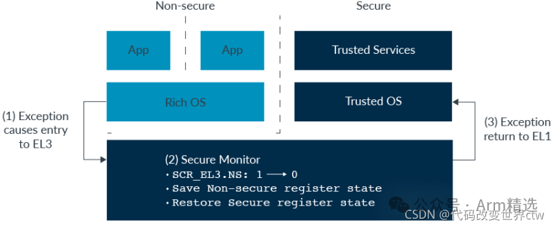 Trusted Firmware is an open-source project from Arm that provides a reference implementation of the Secure Monitor. We will discuss Trusted Firmware later in this article.
A few registers are banked according to security state. This means that the register has two copies, and the core will automatically use the copy belonging to the current security state. When the system registers are banked, we use (S) and (NS) to indicate which copy we are referencing. For example, ICCBPR1EL1(S) and ICCBPR1EL1(NS). Note: In Armv6 and Armv7-A, most system registers are banked according to security state. Currently, general-purpose registers and vector registers are still banked.
3.3. Virtual Address Space
We know that ARM has the concept of virtual addresses and the concept of MMU page table translation. For example, EL0/1 has a translation regime, and EL2 has a separate translation regime, as shown below: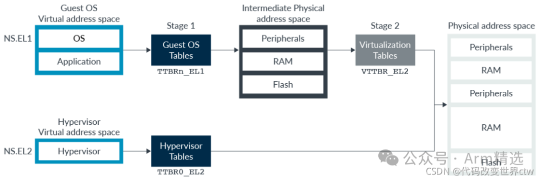
Secure and non-secure states also have separate translation regimes. For example, there are Secure EL0/1 translation regimes and Non-secure EL0/1 translation regimes, as shown below: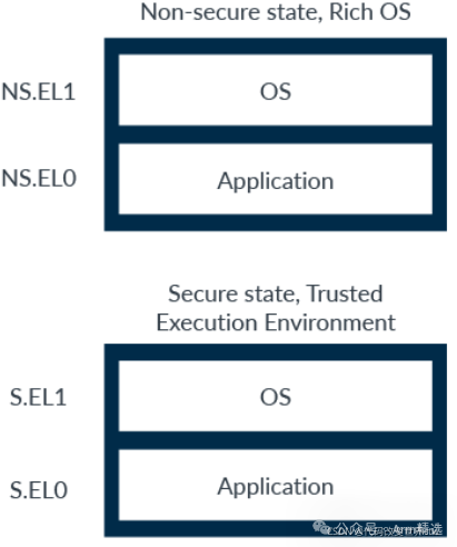
When writing addresses, a prefix is used to indicate the referenced translation mechanism:
-
NS.EL1:0x8000 – Virtual address 0x8000 in the Non-secure EL0/1 translation mechanism
-
S.EL1:0x8000 – Virtual address 0x8000 in the Secure EL0/1 translation mechanism
It is important to note that S.EL1:0x8000 and NS.EL1:0x8000 are two different and independent virtual addresses. The processor will not use the NS.EL1 translation in the secure state, nor will it use the S.EL1 translation in the non-secure state.
3.4. Physical Address Space
In addition to the two security states, the TrustZone architecture also provides two physical address spaces: secure and non-secure.
-
In the non-secure state, virtual addresses are always translated to non-secure physical addresses. This means that software operating in the Non-secure state can only see Non-secure resources and will never see Secure resources. This is illustrated here:
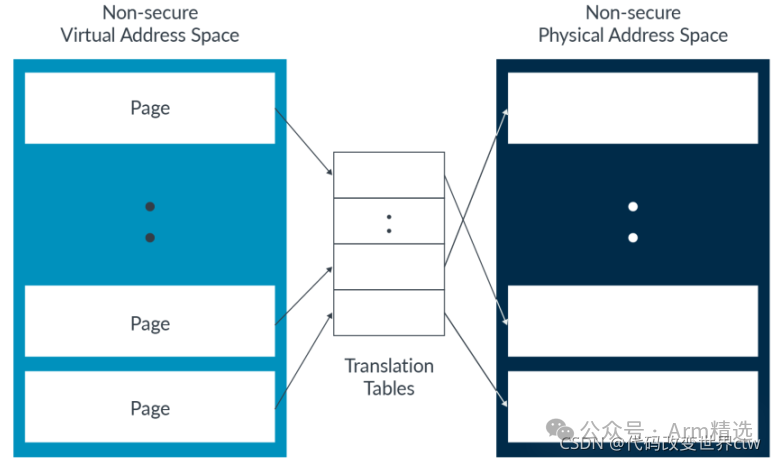
Think: In the non-secure state, if I forcibly change NS in the entry to 0, how does the MMU translate? Will it translate to the secure physical address, or will it report an error when accessing?
-
In the secure state, software can access both secure and non-secure physical address spaces. The NS bit in the translation table entry controls which physical address space the virtual memory block or page translates to, as shown in the figure below:
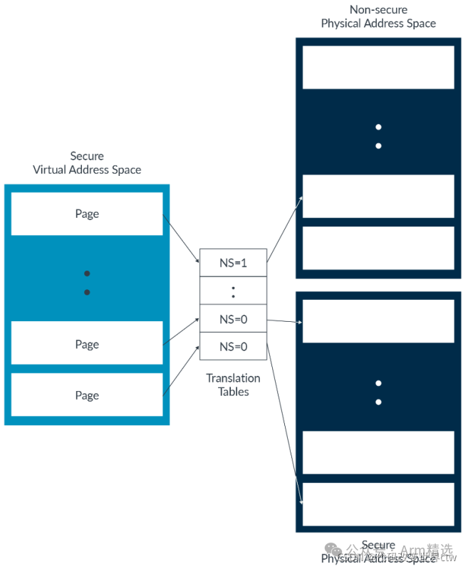
Note: In the Secure state, when Stage 1 MMU is disabled, all addresses are treated as Secure.
Just like virtual addresses, prefixes are typically used to identify the referenced address space. For physical addresses, these prefixes are NP: and SP:. For example:
-
NP:0x8000 – Address 0x8000 in the Non-secure physical address space
-
SP:0x8000 – Address 0x8000 in the Secure physical address space
It is important to note that secure and non-secure are different address spaces, not just attributes like readable or writable. This means that NP:0x8000 and SP:0x8000 in the previous example are different memory locations, treated as different memory locations by the processor.
Note: It is more helpful to think of the address space as having extra address bits on the bus.
3.5. Cache
In the Arm architecture, data caches are physically tagged (i.e., physical TAG). Physical addresses include which address space the line comes from, as shown below: 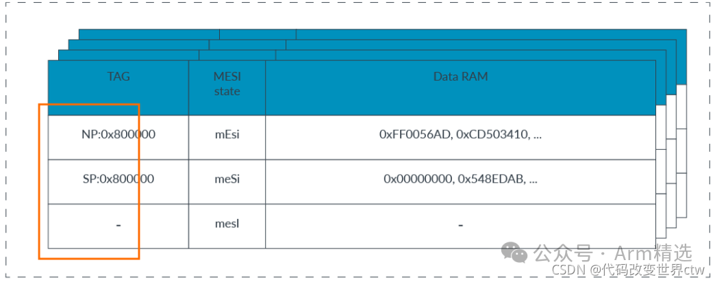 Cache lookups on NP:0x800000 will never hit the cache line marked SP:0x800000. This is because NP:0x800000 and SP:0x800000 are different addresses.
This also affects cache maintenance operations. Consider the example data cache in the figure above. If the virtual address va1 maps to the physical address 0x800000, what happens when software issues <span>DC IVAC</span><span>,</span><span>va1</span> (data or unified cache line invalidation by virtual address) from the Non-secure state?
The answer is that in the non-secure state, all virtual addresses are translated to non-secure physical addresses. Therefore, va1 maps to NP:0x800000. The cache operates only on the line containing the specified address, in this case, NP:0x800000. The line containing SP:0x800000 is unaffected.
For set/way operations, such as <span>DC ISW</span><span> or </span><span>Xt</span>, operations issued from the non-secure state will only affect lines containing non-secure addresses. Set/way operations from the secure state will affect lines containing both secure and non-secure addresses.
This means that software can only fully invalidate or clear the entire cache in the secure state. From the non-secure state, software can only clear or invalidate non-secure data.
3.6. TLB: Translation Lookaside Buffer
The Translation Lookaside Buffer (TLB) caches the most recently used translations. The processor has multiple independent translation mechanisms:. The entries in the TLB can be identified by security state and Exception Level, indicating which translation regime they belong to. The structure of the TLB is implementation-defined, and the figure below shows an example: 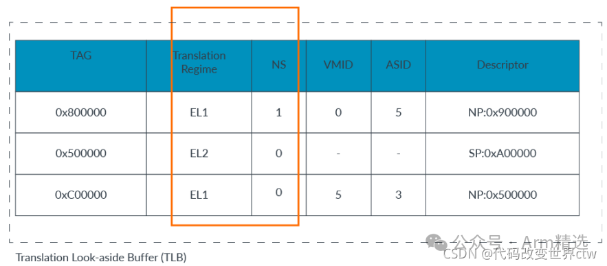
When software issues a TLB invalidation operation (TLBI instruction) at EL1 or EL2, it targets the current security state. Therefore, a <span>TLBI ALL E1</span> issued from the secure state can only invalidate all cached entries in the S.EL0/1 translation mechanism.
EL3 is a special case. As mentioned earlier regarding security states, when at EL0/1/2, the SCR_EL3.NS bit controls which security state the processor is in. However, EL3 is always in a secure state, regardless of the SCR_EL3.NS bit. In EL3, SCR_EL3.NS allows software to control which security states TLBI operations target.
For example, executing <span>TBLI ALL E1</span> at EL3:
-
SCR_EL3.NS==0: Affects the secure EL0/1 translation mechanism
-
SCR_EL3.NS==1: Affects the non-secure EL0/1 translation mechanism
3.7. SMC Exceptions
As part of support for the two security states, the architecture includes the Secure Monitor Call (SMC) instruction. Executing an SMC results in a Secure Monitor Call exception targeting EL3.
SMC is typically used to allow requests for services from firmware running in EL3 or hosted in a Trusted Execution Environment. After the SMC instruction is called, the PE targets EL3, and the SMC dispatcher determines which entity will handle it. As shown in the figure below: 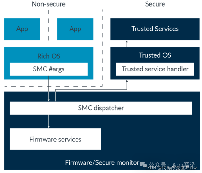 To standardize the interface, Arm provides
 <span>SMC</span><span> Calling</span><span> Convention</span><span>(</span><span>DEN0028</span><span>)</span> and <span>Power</span><span> State</span><span> Coordination</span><span> Interface</span><span> specification</span><span>(</span><span>DEN0022</span><span>)</span>. These specifications outline how to use SMC to request services.
Executing SMC at EL1 may be captured by EL2. This is useful for hypervisors, as the hypervisor may want to simulate the firmware interface seen by virtual machines.
Note: The SMC instruction is not available at EL0 in both security states.
3.8. Secure Virtualization
When virtualization was first introduced in Armv7-A, it was only added in the non-secure state. Prior to Armv8.3, this was also the case for Armv8, as shown in the figure below: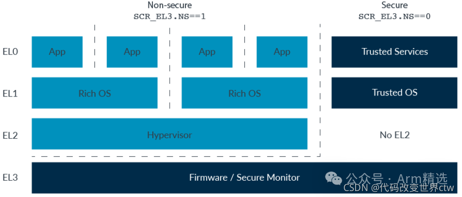
As previously mentioned regarding switching between security states, EL3 is used to host firmware and the Secure Monitor. Secure EL0/1 hosts the Trusted Execution Environment (TEE), which consists of trusted services and a kernel. There is no need for multiple virtual machines in the secure state. This means that virtualization support is not required. As the adoption of TrustZone increases, several requirements have become evident:
-
Some trusted services are associated with specific trusted kernels. For devices supporting multiple services, it may be necessary to run multiple Trusted kernels.
-
Following the principle of least privilege, certain firmware functions need to be moved out of EL3.
Why was S-EL2 introduced? The above two points provide the background or history or requirements!
The solution is to introduce support for EL2 in the secure state, which was provided with Armv8.4-A, as shown in the figure below: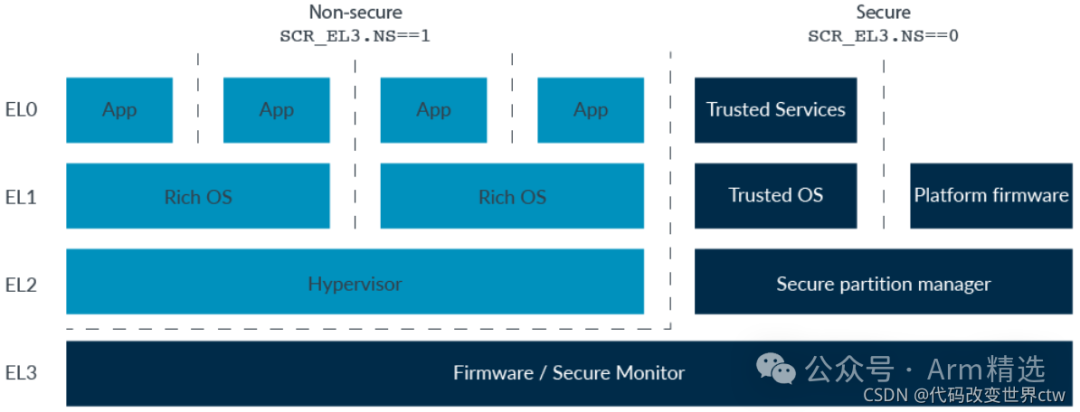 S.EL2 typically hosts the Secure Partition Manager (SPM), rather than a full hypervisor. SPM allows the creation of isolated partitions that cannot view the resources of other partitions. A system can have multiple partitions containing trusted kernels and their trusted services.
It is also possible to create a partition to house platform firmware, eliminating the need to run that code at EL3.
Enabling Secure EL2 When S.EL2 is supported, it can be enabled or disabled. Whether S.EL2 is enabled is controlled by the SCR_EL3.EEL2 bit:
-
0: Disable S.EL2, behavior is the same as a processor that does not support S.EL2
-
1: Enable S.EL2
Stage 2 Translation in Secure State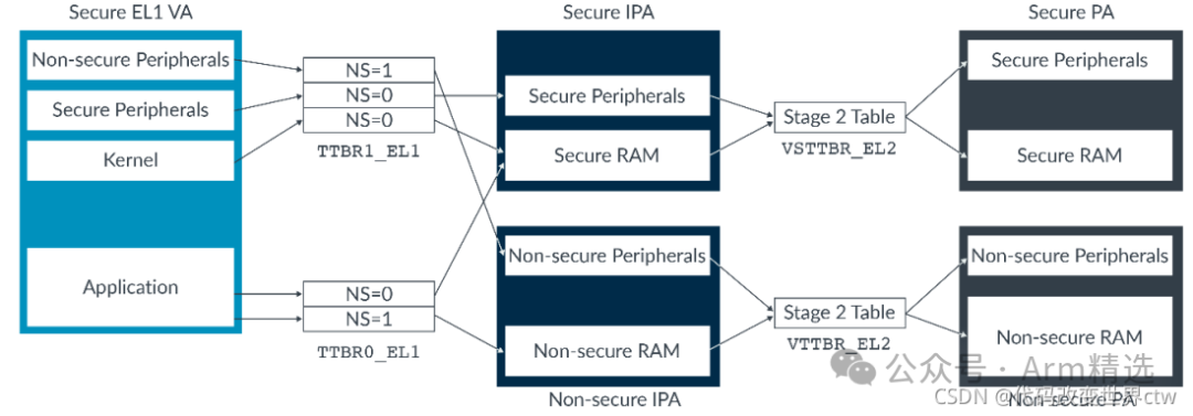 Unlike Stage 1 tables, Stage 2 table entries do not have an NS bit. For a given IPA space, all translations will produce secure or non-secure physical addresses, controlled by register bits. Typically, non-secure IPAs translate to non-secure PAs, while secure IPAs translate to secure PAs.
4. TrustZone Technology in System Architecture
So far in this article, we have primarily focused on processors, but TrustZone is not just a set of processor features. To leverage TrustZone capabilities, we also need support from the rest of the system.
Here is an example of a system enabling TrustZone: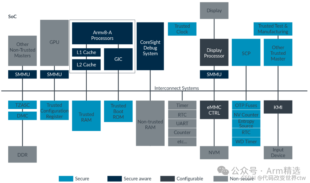 This section will continue to discuss the relevant components and their roles in TrustZone.
4.1. Peripherals and Memory
In the previous section on physical address space, we introduced the concept of two physical address spaces: secure and non-secure. The processor exports the address space being accessed to the memory system. The memory system uses this information to enforce isolation.
In this article, we refer to bus secure and bus non-secure. Bus secure refers to bus access to secure physical address space. Bus non-secure means bus access to non-secure physical address space. However, software in a secure state can access both physical address spaces. This means that the security state of the bus access does not necessarily match the security state of the PE.
Note: In AMBA AXI and ACE, the AxPROT[1] signal is used to specify which address space is being accessed. Similar to the NS bit in the translation table, 0 indicates secure and 1 indicates non-secure.
Theoretically, a system can have two completely independent memory systems, using the accessed physical address space (AxPROT) to choose between them. In practice, this is not feasible. Instead, the system uses the physical address space as an attribute to control access to different devices in the memory system.
4.3 Enforcing Isolation
TrustZone is sometimes referred to as a slave protection system. The host issues a security signal for access, and the memory system decides whether to allow the access. How is the memory system-based check accomplished?
In most modern systems, the memory system-based check is accomplished by the interconnect. For example, the Arm NIC-400 allows system designers to specify for each connector:
-
Secure only allows secure access. Non-secure access will result in a fault.
-
Non-secure only allows non-secure access. Secure access will result in a fault.
-
Boot time configurable At boot time, system initialization software can program the device as secure or non-secure. Defaults to secure.
-
TrustZone aware allows all accesses.
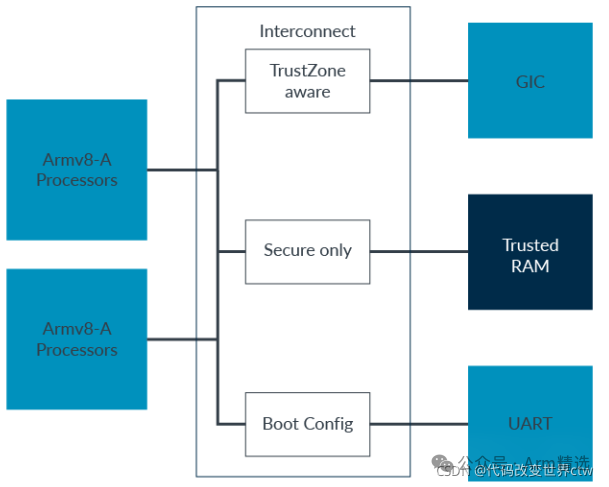 This approach applies to TrustZone-aware devices or those fully located within a single address space. For larger memories, such as off-chip DDR, we may want to partition the memory into secure and non-secure areas. The TrustZone Address Space Controller (TZASC) allows us to do this, as shown in the figure below:
 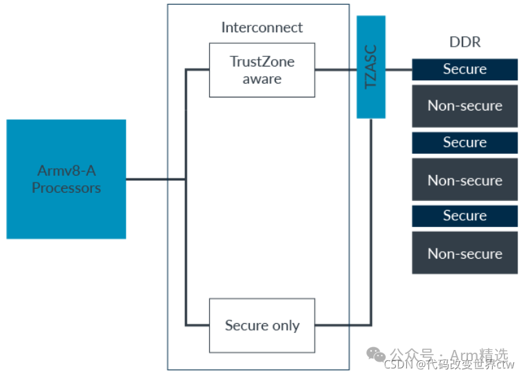 TZASC is similar to a Memory Protection Unit (MPU), allowing the device’s address space to be split into multiple regions. Each region is designated as secure or non-secure. The registers controlling TZASC can only be accessed securely, allowing only secure software to partition the memory.
An example of TZASC is the Arm TZC-400, which supports up to nine regions. Note that this is nine, with region 0 also counted.
Note: Off-chip memory is not as secure as on-chip memory, as attackers can more easily read or modify its contents. On-chip memory is more secure but is more expensive and limited in size. As always, we must balance cost, availability, and security. Care should be taken when deciding which assets need to be in off-chip memory and which should be retained on-chip.
4.4 Bus Masters
Next, we will look at the bus masters in the system, as shown in the figure: 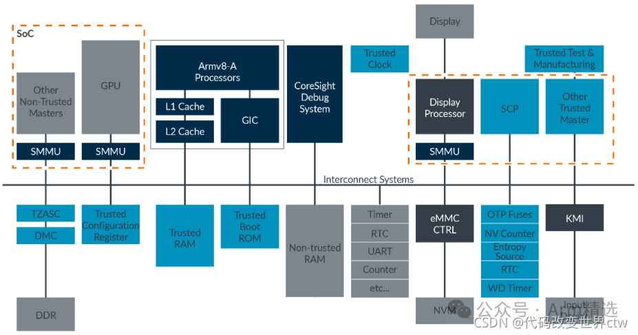 A-profile processors in the system can recognize TrustZone and send the correct security state with each bus access. However, most modern SoCs also include non-processor bus masters, such as GPUs and DMA controllers.
Similar to slave devices, we can roughly categorize the masters in the system into several groups:
-
TrustZone aware Some masters support TrustZone and provide appropriate security bits for each bus access, just like processors. Examples in this regard include the System MMU (SMMU) built according to the Arm SMMUv3 specification.
-
Non-TrustZone aware Some traditional IP does not support TrustZone. Such masters typically do not provide security bits for their bus access or always send the same value.
-
Design time tie-off In cases where a master needs to access only a single physical address space, system designers can tie off the appropriate signals to fix the address space it can access. This solution is simple but not flexible.
-
Configurable logic Provides logic to add security information to master bus accesses. For example, Arm NIC-400 provides registers that secure software can use at boot time to set the security of additional master accesses. This overrides any values provided by the master itself. This approach still only allows the master device to access a single physical address space but is more flexible than tie-off.
-
SMMU A more flexible option is SMMU. For trusted masters, the SMMU behaves similarly to an MMU in a secure state. This includes the NS bit in the translation table entry, controlling which physical address space is accessed.
4.5 M and R Profile Arm Processors
Many modern designs include a mix of A, R, and M profile processors. For example, a mobile device may have an A-profile processor running the mobile operating system, an R-profile processor for the cellular modem, and an M-profile processor for low-level system control. The figure below shows an example mobile device and the different processors you might find: 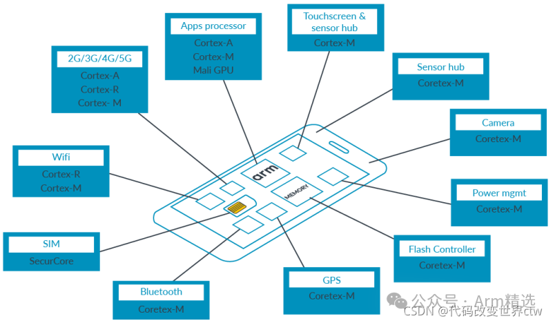
R profile does not support two security states like the A profile. This means that software running on these processors cannot control the output physical address space. In this way, their behavior is very similar to other masters that do not support TrustZone. The same is true for M profile processors that have not implemented TrustZone for Armv8-M.
Typically, these processors only need to access a single physical address space. Using our mobile device example, the processor often includes an M profile processor for low-level system control. This is sometimes referred to as the System Control Processor (SCP). In many systems, the SCP will be the only secure device. This means it only needs to generate bus secure accesses.
4.6 Interrupts
Next, we will look at interrupts in the system, as shown in the figure: 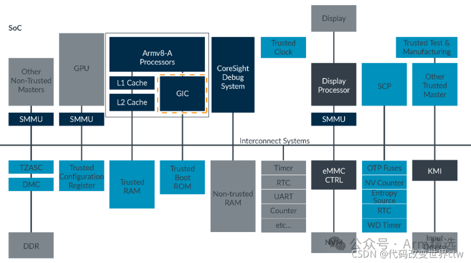 The Generic Interrupt Controller (GIC) supports TrustZone. Each interrupt source, referred to as INTID in the GIC specification, is assigned to one of three groups:
-
Group 0: Secure interrupt, signaled as FIQ
-
Secure Group 1: Secure interrupt, signaled as IRQ or FIQ
-
Non-secure Group 1: Non-secure interrupt, signaled as IRQ or FIQ
This is controlled by writing to the <span>GIC</span><span>[</span><span>D</span><span>|</span><span>R</span><span>]</span><span>_IGROUPR</span><span><n></span> and <span>GIC</span><span>[</span><span>D</span><span>|</span><span>R</span><span>]</span><span>_IGRPMODR</span><span><n></span> registers, which can only be done in a secure state. The assignments are not static. Software can update the assignments at runtime.
For INTIDs configured as secure, only bus secure accesses can modify their state and configuration. For non-secure bus accesses, the register fields corresponding to the secure interrupts are read as 0.
For INTIDs configured as non-secure, both secure and non-secure bus accesses can modify their state and configuration.
Why are there two secure groups? Generally speaking, Group 0 is used for interrupts processed by EL3, while S-Group 1 is used for handling interrupts in S.EL2/S.EL1/S.EL0.
4.7 Handling Interrupts
The processor has two interrupt exceptions, IRQ and FIQ. When an interrupt becomes pending, the GIC uses different interrupt signals based on the interrupt group and the current security state of the processor: 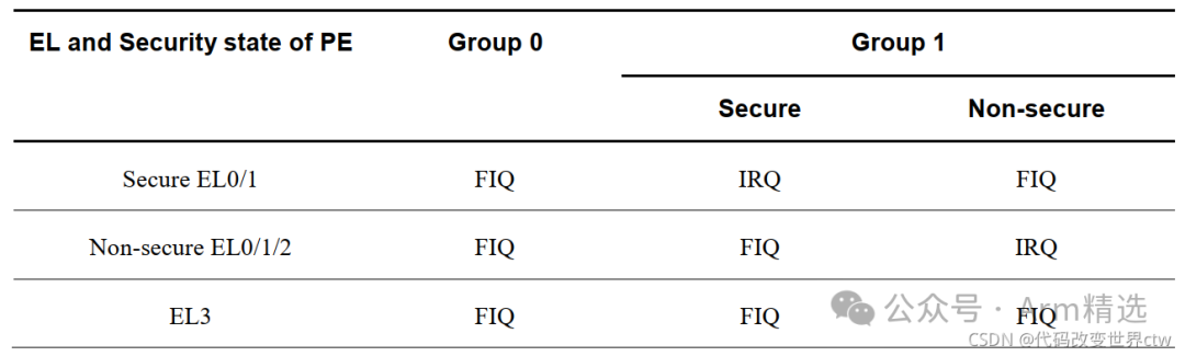 The figure below also shows an example of interrupt routing: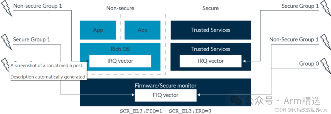
4.8 Debug, Trace, and Profiling
Next, we will look at the debugging and tracing components in the system, as shown in the figure: 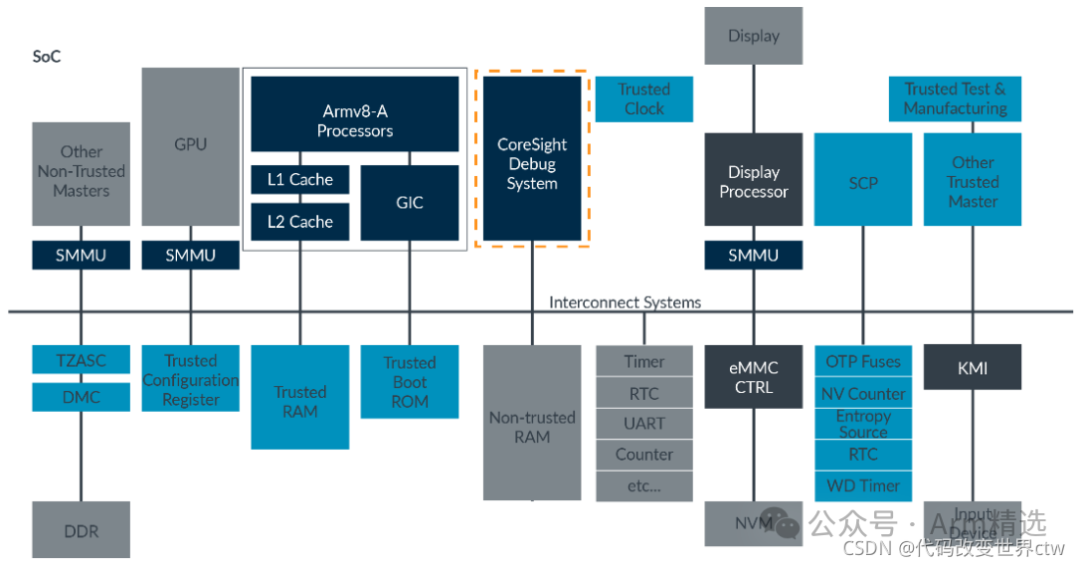 Modern Arm systems include extensive capabilities to support debugging and analysis. With TrustZone, we must ensure that these capabilities are not used to compromise the security of the system.
Regarding debugging capabilities, consider the development of a new SoC. Different developers may debug different parts of the system. Engineers from the chip company need to be trusted to debug all parts, including secure state code. Therefore, all debugging capabilities should be enabled.
When the chip is shipped to OEMs, they still need to debug the non-secure state software stack. However, OEMs may be prevented from debugging secure state code.
In the shipped products containing that chip, we may need to provide some debugging capabilities for application developers. But we also want to limit the ability to debug code from chip vendors and OEMs.
Enabling different debugging, tracing, and analysis capabilities signals can help us manage this situation. This includes separate signals for controlling the use of capabilities in secure and non-secure states.
Continuing with a debugging example, signals include:
-
DBGEN – Top-level debug enable, controls external debugging in both security states
-
SPIDEN – Secure debug enable, controls external capability to debug in secure state
Note: These two signals are examples. There are other debugging authentication signals. For a complete list, refer to the technical reference manual of the processor.
Here is an example of how to use these two debug signals:
-
In the early stages of chip design and development, enable all debug options: DGBEN==1, SPIDEN==1
-
In the OEM product development stage, only enable non-secure side debug options: DGBEN==1, SPIDEN==0
-
After product shipment, disable all debug options: DGBEN==0, SPIDEN==0
Since we need different signal values at different development stages, we typically use efuse values to feed back this signal 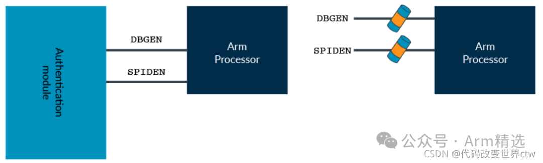
4.9 Other Devices
Finally, we will look at other devices in the system, as shown in the figure: 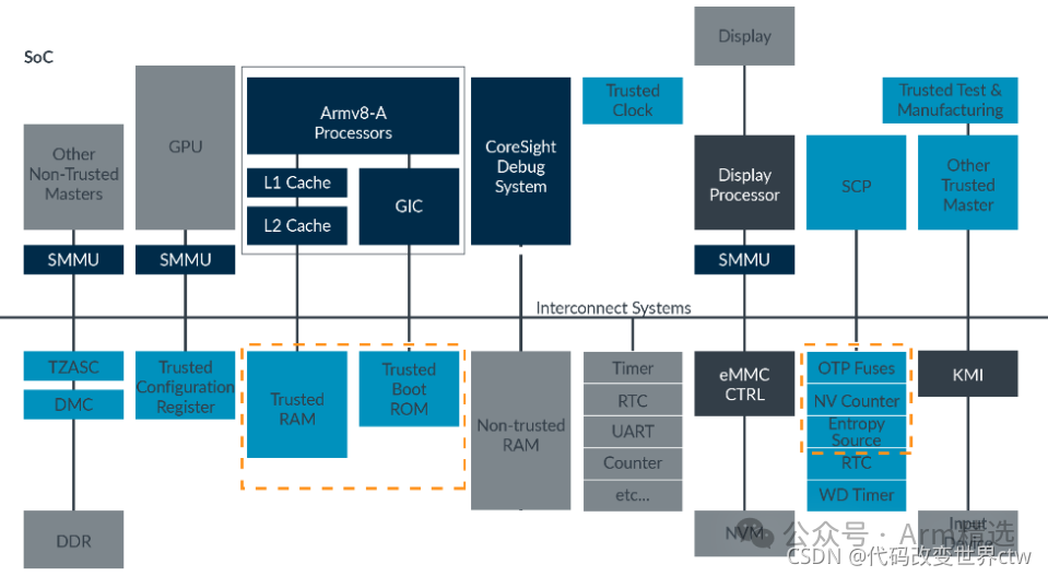 Our system example enabling TrustZone includes several devices that we have not yet covered but are necessary for building practical systems. • One-time programmable memory (OTP) or fuses • Non-volatile counter (This is a counter that can only increase and can never be reset) • Trusted RAM and Trusted ROM
Latest Listings☞【Course】HSM/HSE/SHE/SE/Crypto engine Overview☞【Course】Introduction to keystore/keymaster/keymint☞【Course】Arm Microarchitecture and Arm MMU/SMMU Discussion Class☞【Course】TEE Overview Course – TEE/Security Interview CourseClassic Course☞【Membership】Arm Selected Classroom – Platinum VIP Introduction  ☞【Course】”From Beginner to Expert in ARMv8/ARMv9 Architecture” – Phase II Video Course ☞【Course】TrustZone/TEE/Security from Beginner to Expert – Standard Version Video Course ☞【Course】Secure Boot from Beginner to Expert (Phase II) ☞【Course】CA/TA Development from Beginner to Expert☞【Course】”ATF Architecture Development Explained” – Video Course☞【Course】”OP-TEE System Development Explained” – Video Course☞【Course】ATF/OP-TEE/Hafnium/Linux/Xen Code Reading☞【Guide】[Guide] Four Ways to Watch Our Courses☞【Guide】What is the Difference Between Phase I and Phase II of Arm Video Courses?☞【Guide】What are the Differences Between the Replays, Standard, and High-Configuration Versions of TrustZone/TEE/Security from Beginner to Expert?
【Store Address】

【Customer Service Consultation】