ver0.2
Introduction
Previously, we introduced the core content of the General Interrupt Controller (GIC), an important component in the ARM architecture. Through a series of preceding articles, we elaborated on the system architecture of GIC, core components, interrupt types, interrupt signal routing mechanisms, state machine management, interrupt priorities, and other fundamental concepts. We believe that you can now construct a framework for interrupts in the ARM architecture in your mind. When introducing the types of interrupts supported by GIC, we learned that the current GIC architecture supports four types of interrupts: SPI, PPI, SGI, and LPI. In previous articles, we mostly relied on SPI, PPI, and SGI to outline the working principles and processes of GIC. We know that ARM’s ambition has never been limited to the embedded domain but extends to the vast world of computing, making continuous efforts in the PC and server fields. In this context, traditional interrupt allocation methods (SPI, PPI, SGI) may not enable the system to efficiently handle interrupts, especially in complex multi-cluster system environments. LPI was born to alleviate this bottleneck as a new type of interrupt. LPI interrupts are based on the principle of locality, allowing interrupts to be allocated more precisely to specific CPU-PE or CPU-Cluster, thereby improving interrupt handling efficiency and system performance. It is a new feature introduced in GICv3 and higher versions, providing a more flexible and efficient solution for interrupt management in multi-core systems. In this article, we will explore the mechanism of this new type of interrupt under the GIC framework. Also, before starting this article, we hope you can read some preceding articles to get a feel for it:
(1) [V-02] Virtualization Basics – CPU Architecture (based on AArch64)
(2)[V-05] Virtualization Basics – Exception Model (AArch64)
(3)[A-25] ARMv8/v9-GIC System Architecture (Hardware Basics of Interrupts)
(4)[A-26] ARMv8/v9-GIC Interrupt Types
(5)[A-27] ARMv8/v9-GIC Core Components (Basic Components of Interrupt Programming)
(6)[A-28] ARMv8/v9-GIC Interrupt Signal Routing Mechanism and Strategy
(7)[A-29] ARMv8/v9-GIC – Security Architecture Design of Interrupt Subsystem (Security/FIQ/IRQ)
(8)[A-30] ARMv8/v9-GIC – Interrupt Handling (Interrupt State Machine/Interrupt Lifecycle)
(9)[A-31] ARMv8/v9-GIC – Interrupt Handling (Interrupt Priority/Interrupt Preemption/Interrupt Nesting)
Body
We will still follow the previous approach of introducing traditional interrupt types from the perspectives of system architecture, core components, interrupt states, and routing strategies to introduce GIC’s LPI interrupt type, examining how the LPI interrupt mechanism works and how it differs from the previous three types.
1.1 System Architecture
First, we need to understand the basic hardware environment in which LPI works from the perspective of system architecture, as shown in Figure 1-1.
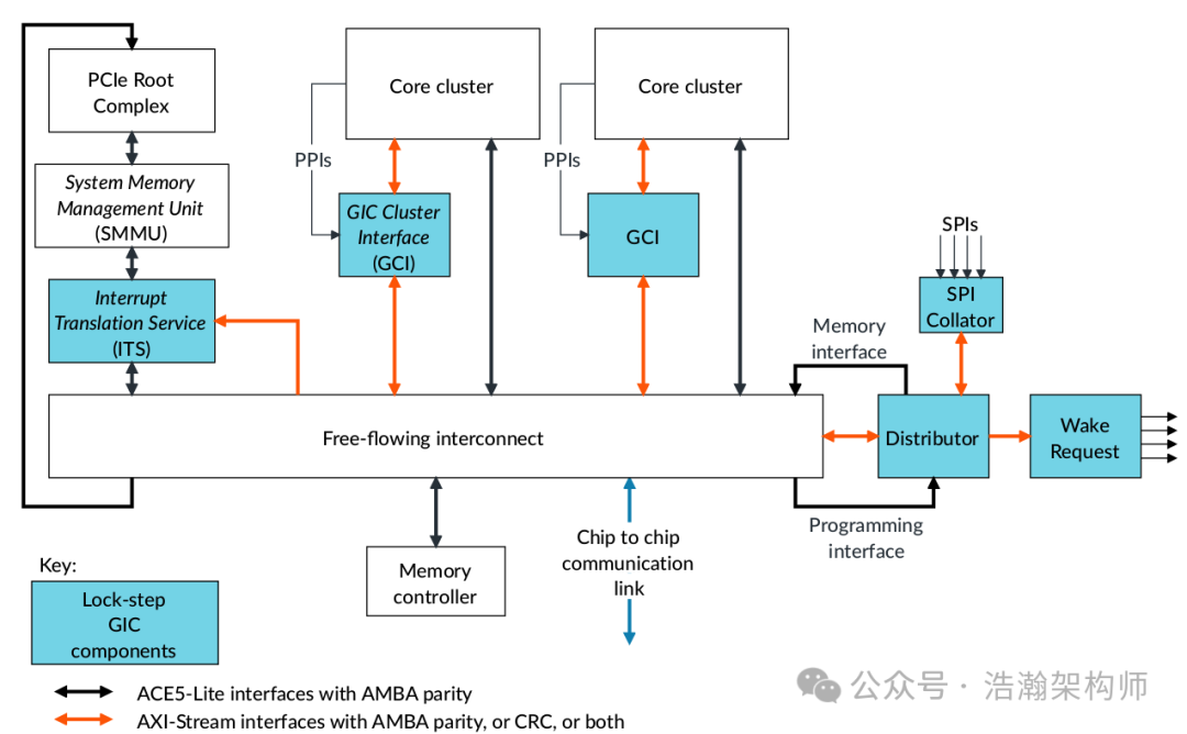
Figure 1-1 GIC-720AE System Architecture
The above figure is just one system layout of GIC-720AE; other layouts can be found in previous articles or by directly consulting the manual. Let’s look at the manual’s description of GIC-720AE (excerpt):
The GIC-720AE provides the following interrupt features:
• Support for the following interrupt types:
◦ Up to 56000 physical Locality-specific Peripheral Interrupts (LPIs). A peripheral generates these interrupts by writing to a memory-mapped register in the GIC-720AE.
◦ Direct injection of up to 56000 virtual LPIs for each virtual processing element (vPE), when the GIC is configured to support GICv4.1.
• Up to 32 Interrupt Translation Service (ITS) modules that provide device isolation and ID translation for message-based interrupts and enable virtual machines to program devices directly.
• Locality-specific Peripheral Interrupts (LPIs) are edge-triggered message-based interrupts that can use an Interrupt Translation Service (ITS), if it is implemented, to route an interrupt to a specific Redistributor and connected PE. GICv3 provides two types of support for LPIs. LPIs can be supported either:
◦ Using the ITS to translate an EventID from a device into an LPI INTID.
◦ By forwarding an LPI INTID directly to the Redistributors, using GICR_SETLPIR.
From the manual’s description, we can summarize:
(1) The latest version (GICv3) of the GIC controller supports LPI-type interrupts, which are based on message signaling over the system bus (message-type interrupt communication method, which we have introduced in the article on interrupt types, so we won’t elaborate on it here).
(2) GICv3 introduces a new component, ITS, to deliver LPI-type interrupts within the GIC system architecture.
(3) LPI-type interrupt signals can be forwarded to specific PE-Cores either through ITS or directly to the GIC-Redistributor.
For situations where devices directly control the GIC-Redistributor’s register GICR_SETLPIR to deliver LPI interrupts, this article will not elaborate; we will only provide a schematic diagram (as shown in Figure 1-2) for those interested to consult the manual.
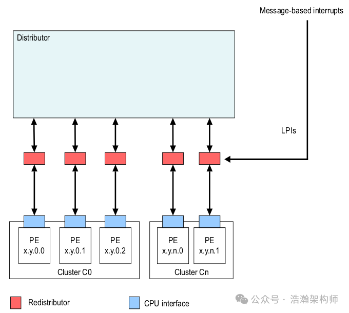
Figure 1-2 Triggering LPIs in an implementation without an ITS
1.2 ITS
Through the introduction of the previous section, the GIC component has configured a new component, ITS, to relay the corresponding LPI signals to specific PE-Cores for processing. Let’s get to know this ITS component, as shown in Figure 1-3:
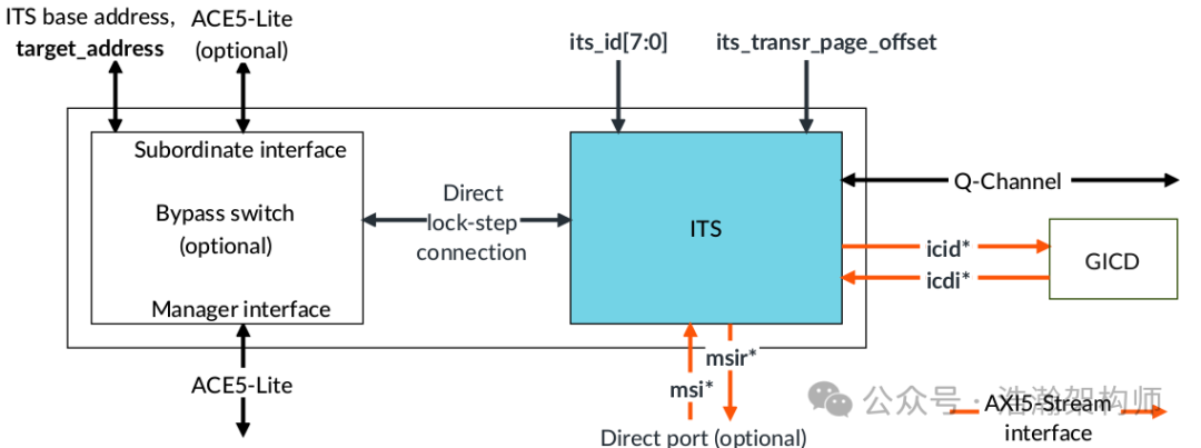
Figure 1-3 ITS Block
Next, let’s look at some descriptions of the core features of ITS from the manual:
• The Interrupt Translation Service (ITS) provides a software mechanism for translating message-based interrupts into LPIs or vLPIs.
• An ITS can be placed anywhere in the system so that it is seen by devices that want to send MSIs.
• The GIC-720AE Interrupt Translation Service (ITS) functions are controlled through registers that are identified with the prefix GITS.
• Interrupts to be translated by the GIC-720AE Interrupt Translation Service (ITS) are identified by EventIDs that are written to GITS_TRANSLATER, the ITS Translation Register.
• Virtual SGIs to be injected directly into a virtual machine are written to the ITS translation register GITS_SGIR.
This section summarizes that ITS also controls and configures the collection and distribution of LPI signals through internal registers. Here we list some registers as shown in Figure 1-4:
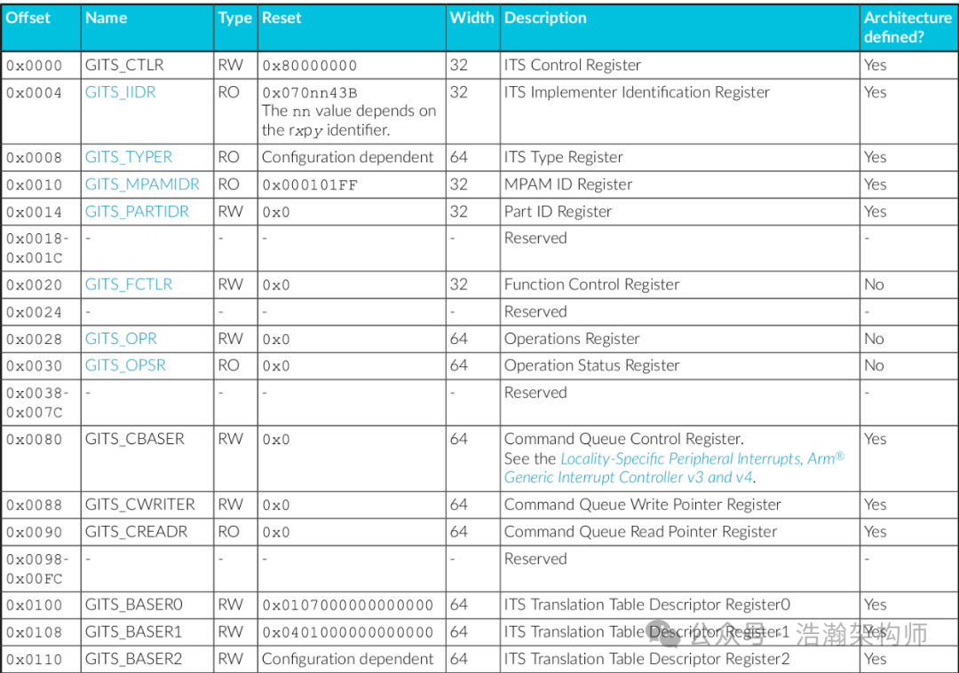
Figure 1-4 ITS control registers
From the above, we can see that ITS works with registers similarly to other core components of GIC, such as Distributor, Redistributor, and Cluster-IF, but the specific working principles differ, which will be explained in later sections of this article.
Additionally, ITS can also be utilized by the Hypervisor to serve internal virtual interrupt signals (we will discuss interrupt virtualization in the ARM architecture in subsequent articles).
1.3 LPI States
The other interrupt types in GIC have four states: Inactive, Pending, Active, Active and Pending, whereas LPI states are simpler, having only two as shown in Figure 1-5:
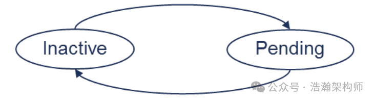
Figure 1-5 State machine for LPIs
The transition of the LPI state machine is also quite simple:
LPIs do not have an active and pending state and transition to the inactive state upon being acknowledged by a PE.
In addition to having fewer states than the three traditional interrupt types (SPI, PPI, SGI), another difference is that the states of traditional interrupt types are maintained in the internal registers of GIC. For example, the Active state of SPI-type interrupts is maintained in the internal register GICD_ISACTIVER<n> of GICD. In contrast, the states of LPI-type interrupts are maintained in memory:
• Software configures the LPI Pending tables, using the implemented range of valid LPI INTIDs, by writing to GICR_PENDBASER. This register provides the base address of the LPI Pending table for physical LPIs.
• Each Redistributor maintains entries in a separate LPI Pending table that indicates the pending state of each LPI when GICR_CTLR.EnableLPIs = 1 in the Redistributor:
◦ 0 The LPI is not pending.
◦ 1 The LPI is pending.
• Because there are only two states, there is only 1 bit for each LPI in the LPI Pending tables.
• The interrupt controller must be able to read from and write to the memory allocated for the LPI Pending table. Typically, a Redistributor caches the highest priority pending interrupts internally and writes state information to the LPI Pending table when there are too many pending interrupts to cache or when entering a low-power state.
While LPIs are enabled in the owning Redistributor, software is never expected to directly access the LPI Pending table.
We can summarize the manual’s description as follows:
(1) To maintain the state of each LPI-type interrupt, due to its unique link-layer communication (bus message) and quantity (8192 and greater), maintaining them within GIC-ITS is clearly impractical, so they are all maintained in memory, referred to as “LPI Pending tables.”
(2) Since each interrupt has only two states, 1 bit is sufficient.
(3) Each GIC-Redistributor can index these “LPI Pending tables” through the internal register GICR_PENDBASER.
(4) Maintaining interrupt states has always been the responsibility of GIC itself; therefore, even though they are in memory, GIC must have the capability to read and access these state bits, while software running on the PE is prohibited from directly accessing these state bits.
1.4 LPI Priorities and Security Groups
After discussing states, let’s talk about priorities and security groups, directly referring to Figure 1-6:
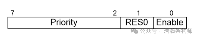
Figure 1-6 Format of an entry in the LPI Configuration table
Let’s look at the introduction in the manual:
• LPI configuration is global.
• The LPI Configuration table contains one byte for each LPI INTID.
• Although priority values are 8 bits for SPIs, PPIs, and SGIs, there are only 6 bits in the table to record the priority of an LPI. The lower two bits of the priority of an LPI are always treated as 0b00.
• There is no field for recording the Group configuration. LPIs are always treated as Non-secure Group 1 interrupts.
• The interrupt controller must be able to read the memory allocated for the LPI Configuration table. However, it never writes to this memory.
Combining the manual, we summarize as follows:
(1) Similar to the state management of LPIs in memory, the priorities of LPIs are also managed in memory through the LPI Configuration table. Note that the table is singular, indicating that this LPI Configuration table is global within the system.
(2) The LPI Configuration table allocates 6 bits for priority description, while the remaining two bits do not describe the security grouping of LPIs (GIC supports three types of secure interrupts: Secure Group 0, Secure Group 1, Non-Secure Group 1) but default all LPIs to Non-secure Group 1.
(3) Since it is in memory, GIC must have the capability to read the LPI Configuration table, but it cannot write to the LPI Configuration table. The initialization and updates of this table can only be permitted through the GIC driver running on the PE.
Regarding the working principle of LPI interrupt priorities, you can refer to the previous article on GIC interrupt priorities; we will not elaborate further here.
1.5 Routing Mechanism
Previously, we mentioned that if peripherals want to send interrupt signals to PE-Cores via LPIs, they must be relayed through ITS to other internal components of GIC (assuming it will be relayed to GIC-Redistributor based on the GIC implementation), as shown in Figure 1-7:
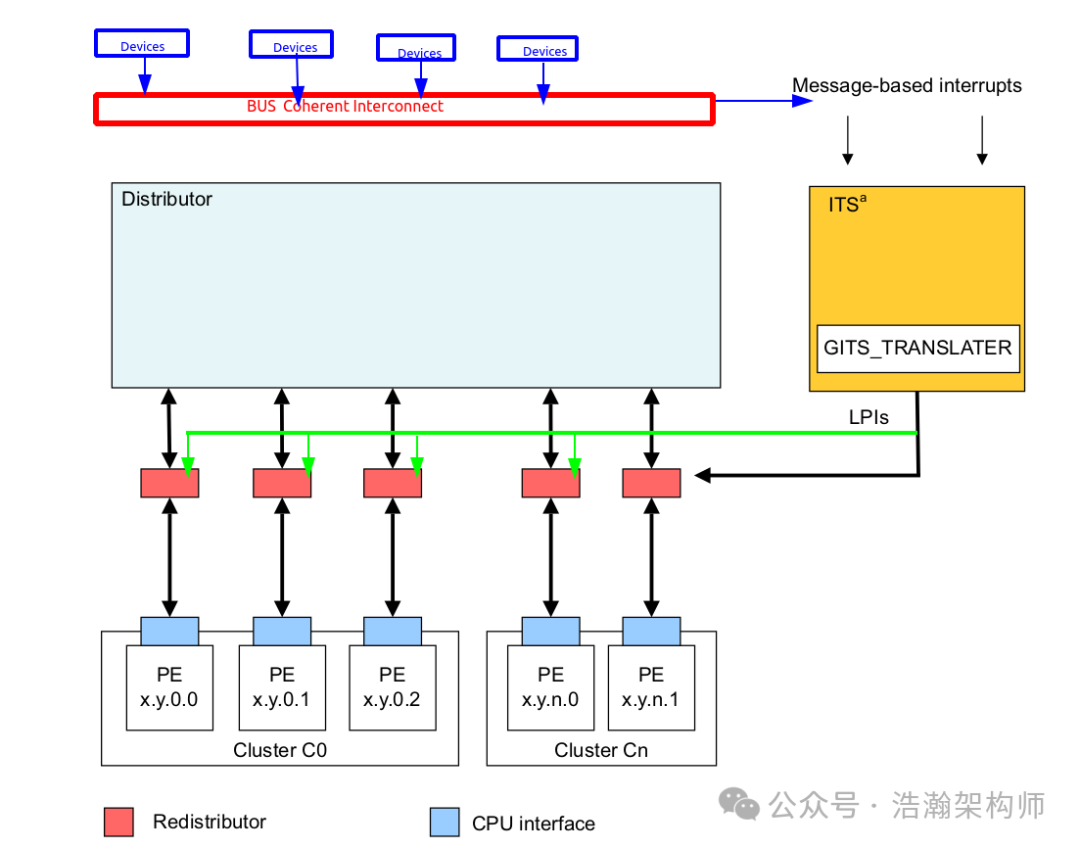
Figure 1-7 Triggering LPIs in an implementation with an ITS
Let’s examine the principle of this routing:
A peripheral generates an LPI by writing a message to GITS_TRANSLATER in the ITS. This provides the ITS with the following information:
EventID
This is the value written to GITS_TRANSLATER. The EventID identifies which interrupt the peripheral is sending. The EventID might be the same as the INTID, or it might be translated by the ITS into the INTID.
DeviceID
The DeviceID identifies the peripheral. The mechanism by which a DeviceID is generated is IMPLEMENTATION DEFINED.
The ITS handles the translation of the message into an INTID that can be delivered to a connected core.
Physical LPIs are grouped together in collections. All LPIs in a collection are routed to the same Redistributor. Software allocates LPIs to collections, allowing it to efficiently move interrupts from one processing element to another.
Routing principle:
(1) The message for LPI interrupts contains (EventID/DeviceID), transmitted through the internal register GITS_TRANSLATER of ITS, as shown in Figure 1-8:

Figure 1-8 GITS_TRANSLATER
Note that the transmission of DeviceID depends on the specific implementation:
GITS_TRANSLATER receives EventID information. It is IMPLEMENTATION DEFINED how the DeviceID is supplied.
(2) The ITS completes the delivery of LPIs according to the pre-configured settings (allocating INTIDs to various Redistributors).
(3) The selection of the Redistributor involves a process similar to address translation based on EventID and DeviceID. Due to the specific implementation of GIC, we will only provide a general process here without going into detailed routines. Interested readers can refer to the manual:
When a peripheral writes a message to GITS_TRANSLATER, the ITS does the following:
• Uses the DeviceID to select the appropriate entry from the Device table. This entry identifies which Interrupt Translation Table to use.
• Uses the EventID to select the appropriate entry from the selected Interrupt Translation Table.
• This entry provides the INTID and the Collection ID.
• Uses the Collection ID to select the required entry in the Collection table, which returns the routing information.
• Forwards the interrupt to the target Redistributor.
The above process is illustrated in Figure 1-9:
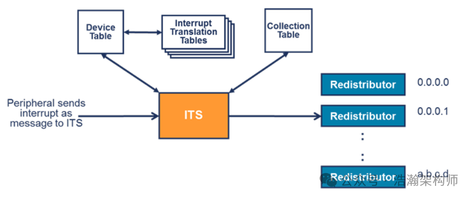
Figure 1-9 An ITS forwarding an LPI to a Redistributor
1.6 Differences between LPIs and Traditional Interrupts
Aside from all interrupt information being transmitted via messaging, we can summarize the following differences based on previous descriptions:
1.6.1 Memory-based Configuration Information
Unlike traditional interrupts, which store most control and configuration information in the internal registers of GIC, LPI interrupts store much of the configuration and routing information in memory, which can be indexed through an internal GIC register, as shown in Figure 1-10.
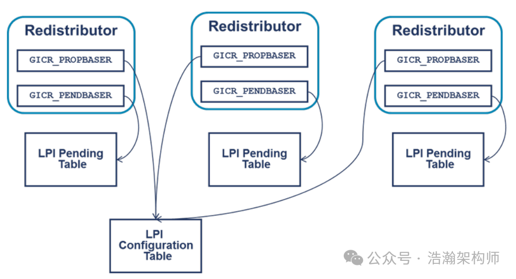
Figure 1-10 LPI Configuration and LPI Pending table
1.6.2 Runtime Maintenance Software-based
Traditional interrupts are primarily managed by GIC after the boot initialization phase, meaning that during runtime, the hardware GIC manages the internal states and configuration information. This is relatively easier to implement in small-scale SOCs, but in large-scale integrated CPU-Clusters, this design pattern faces limitations in system complexity, stability, and cost. The design of LPIs effectively addresses this issue by moving many configurations from within GIC to memory, allowing for more programmable space for PE. Programs running on PE can dynamically adjust strategies (priorities, routing paths, etc.) based on the current system load state, achieving load balancing of interrupt signal processing across various clusters within the SOC. For example, regarding ITS, ARM has designed many commands for maintaining LPI-related information, as shown in Figure 1-11 (excerpt):
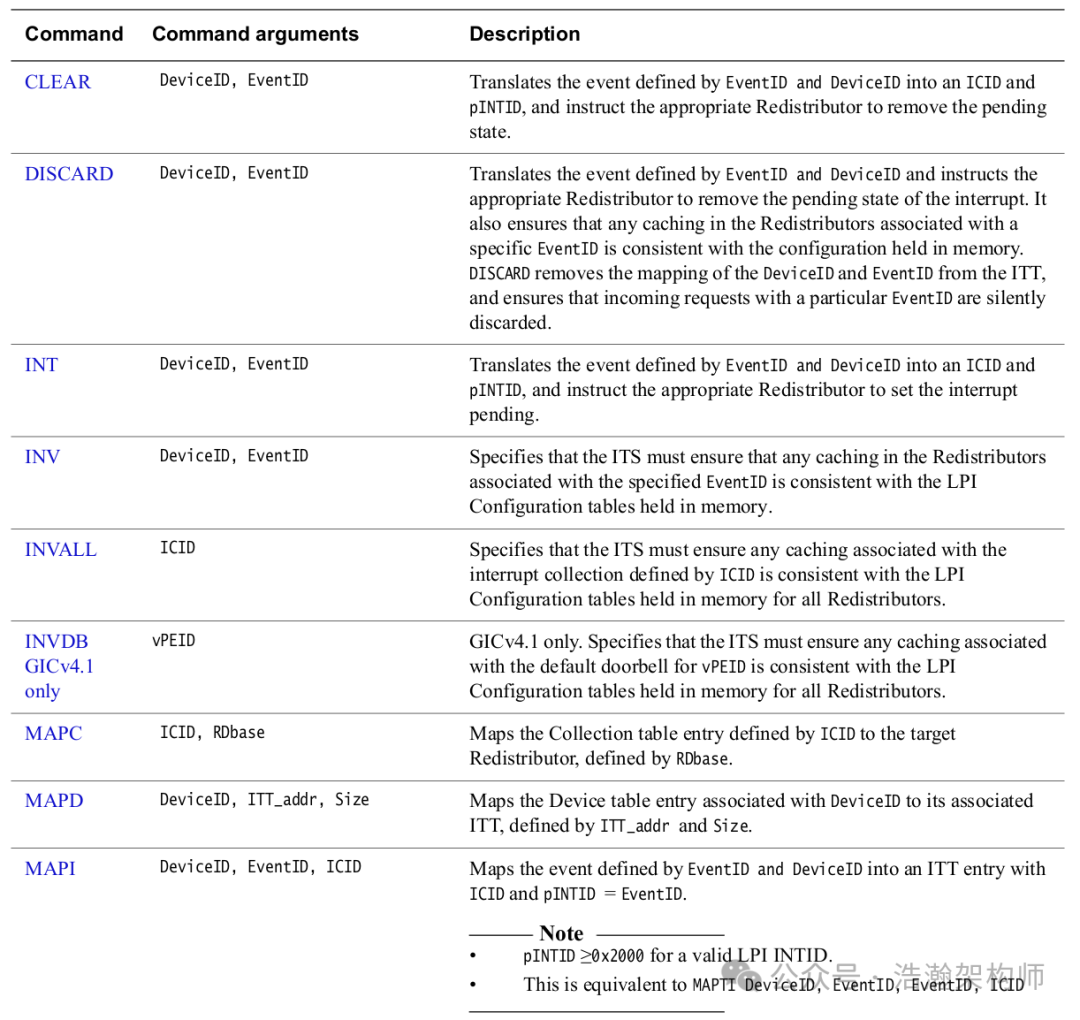
Figure 1-11 ITS commands
Conclusion
Since traditional interrupts are still the main actors in most scenarios using interrupts in the embedded field, LPIs are temporarily not the focus. This article provides a very rough introduction to the background of LPI interrupts, some basic concepts, and the working principles. Many details, such as the traversal process of various tables during routing, have been omitted; interested readers can read the manual for further details. We consider this a preliminary introduction. The main purpose of writing this article is to fill in some gaps from previous articles. We will return to the virtualization track next, discussing topics related to interrupt virtualization in the ARM architecture. Thank you for your attention, please comment, follow, and share.
Reference
[00] <Armv8-A-virtualization.pdf>
[01] <DEN0024A_v8_architecture_PG.pdf>
[02] <learn_the_architecture_aarch64_exception_model.pdf>
[03] <corelink_gic_720ae_generic_interrupt_controller_trm.pdf>
[04] <arm_generic_interrupt_controller_v3_and_v4_virtualization_guide.pdf>
[05] <learn_the_architecture_generic_interrupt_controller_v3_and_v4_lpis.pdf>
[06] <80-ARM-GIC-wx0005_Arm-gicv3_v4学习这一篇就够了.pdf>
[07] <80-ARM-GIC-wx0003_ARM架构Generic-Interrupt-Controller-GIC之Distributor和CPU-interface.pdf>
[08] <80-ARM-GIC-HK0001-一文搞懂GICv3中断控制器的工作原理.pdf>
[09] <80-ARM-GIC-wx0001_ARM-gicv3_gicv4的总结-基础篇.pdf>
[10] <80-ARM-INT-yk0001_万字长文玩转中断:从硬件看中断之GIC.pdf>
[11] <learn_the_architecture_generic_timer.pdf>
[12] <learn_the_architecture_trustzone_for_aarch64.pdf>
[13] <learn_the_architecture_realm_management_extension.pdf>
[14] <locality-specific_peripheral_interrupts_arm_generic_interrupt_controller.pdf>
Glossary
GIC – Generic Interrupt Controller
SCMI – System Control and Management Interface (SCMI)
ACPI – Advanced Configuration and Power Interface (ACPI)
PSCI – Power State Coordination Interface (PSCI)
UEFI – Unified Extensible Firmware Interface (UEFI)
UART – Universal Asynchronous Receiver/Transmitter
SPI – Shared Peripheral Interrupt
PPI – Private Peripheral Interrupt
SGI – Software Generated Interrupts
MPAM – Memory System Resource Partitioning and Monitoring
LPI – Locality-specific Peripheral Interrupt (LPI)
PE – Processing Element
MSI – message-signaled interrupts (MSI)
IAR – Interrupt Acknowledge Registers
EOIR – End of Interrupt Registers
IRM – Interrupt Routing Mode
ITS – Interrupt Translation Service
ITT – Interrupt Translation Tables
vPE – virtual processing element
IPI – inter-processor interrupts
IRI – Interrupt Routing Infrastructure
EOI – End of interrupt
REE – Rich Execution Environment
TEE – Trusted Execution Environment
NMI – Non-Maskable Interrupts
RAZ – Read-As-Zero
WI – Writes Ignored