1. Introduction
The Cortex-M processor series is based on the M-Profile architecture, providing low latency and high determinism for deep embedded systems. Our latest generation Cortex-M processor is the Cortex-M55. The Cortex-M55 is the first processor based on the Armv8.1-M architecture, featuring vector processing extensions with Arm Helium technology. The Cortex-M55 brings higher levels of machine learning and signal processing performance for the next generation of small embedded devices, including wearables, smart speakers, and more.
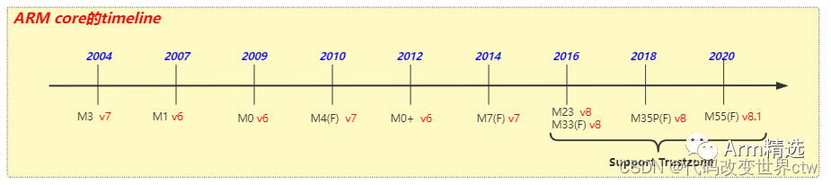
The Cortex-M processors are designed to support the microcontroller market
-
Based on RISC architecture, most instructions are executed in a single cycle
-
Programming is simpler—the entire application can be programmed in C
-
The required functionality is less than that of Cortex-A
Other ARM Core Register and ISA Variations
-
Uses Thumb instructions, does not support the ARM instruction set (i.e., does not support A32, does not support A64)
-
Only the SP in general registers is banked
-
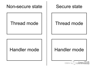
Two operation modes: Thread mode and Handler mode
Different Modes and Exception Models
-
There are only two execution modes: Thread and Handler modes
-
The vector table consists of addresses and does not contain instructions
-
Exceptions automatically save the state (R0-R3, R12, LR, ReturnAddress, RETPSR) onto the stack
Different System Control/Memory Layout
-
The core has a fixed memory mapping
-
No coprocessor C15 – controlled via memory-mapped control registers (MRS, MSR)
ARMv8-M is a 32-bit Load/Store Architecture
-
The only allowed memory access is load and store
-
Most internal registers are 32 bits wide
Programming Model
Two modes: Thread mode and Handler mode, with two execution levels in Thread mode: privileged and unprivileged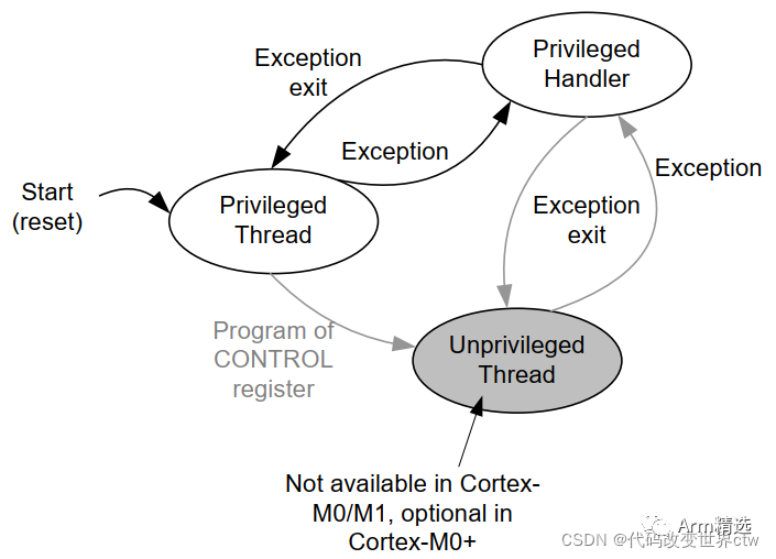
2. Registers
2.1 Summary of Registers
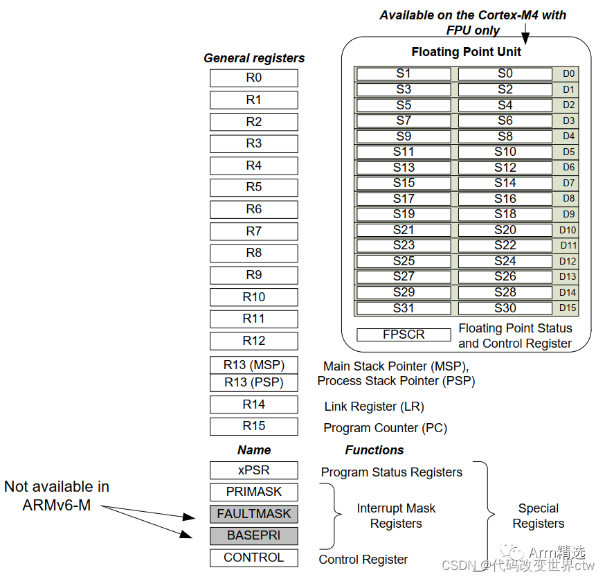
2.1.1 General Registers (All are 32 bits)
-
R0-R12 (Rn).
-
R13 Stack Pointer (SP).
-
R14 Link Register (LR).
- R15 Program Counter (PC)
2.1.2 Special Registers
-
Mask (MASK) Register:
(1) Exception Mask Register: PRIMASK
(2) Priority Mask Register: BASEPRI.
(3) Fault Mask Register: FAULTMASK
-
Control Register: CONTROL
-
Two Stack Pointer Limit Registers: MSPLIM and PSPLIM
-
Program Status Register: Program Status Register (XPSR), includes:
(1) Application Program Status Register (APSR).
(2) Interrupt Program Status Register (IPSR).
(3) Execution Program Status Register (EPSR)
2.1.3 Memory-Mapped Registers
In addition, there are some memory-mapped registers
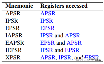
2.2 Introduction to XPSR, APSR, IPSR, and EPSR
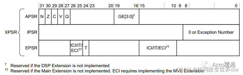
msr and mrs can access these registers in segments
2.2.1 Interrupt Program Status Register (IPSR)
-
When PE is in Thread mode, the IPSR value is 0
-
When PE is in Handler mode,
(1) When an exception occurs, the IPSR saves the exception number of the exception being processed
(2) When calling from Secure state to Non-secure state, the IPSR value is 1
- Using the MRS instruction to forcefully modify the IPSR will not take effect
2.2.2 Execution Program Status Register (EPSR)
The main focus is on the EPSR.T bit
-
0 – Any instruction will produce an INVSTATE error or HardFault
-
The instruction set uses T32
2.3 CONTROL Register
-
Only privileged execution state can write to the control register; both privileged and unprivileged states can read the control register.
-
The architecture requires a context synchronization event to ensure visibility of changes to the CONTROL register
-
When an exception enters or exits, the hardware automatically modifies CONTROL.SPSEL; when PE is in Thread mode, CONTROL.SPSEL can be used to select the stack pointer
3. Instruction Set ISA
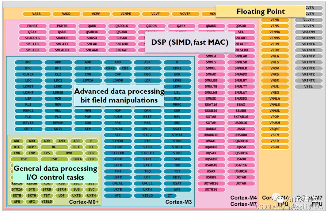
All Cortex-M processors support an instruction set called Thumb. When Thumb-2 technology is available, the full Thumb instruction set becomes quite large when extended. However, different Cortex-M processors support different subsets of instructions available in the Thumb ISA, as shown in the following diagram:
4. Security State
-
If security extensions are implemented, memory regions and other critical resources marked as secure can only be accessed when the PE executes in secure state
-
If security extensions are implemented, the PE will enter Secure state during Cold reset and Warm reset
-
If security extensions are implemented, the PE will enter NON-Secure state during Cold reset and Warm reset
After implementing security extensions, the following registers are banked by security:
-
The R13 (SP) in general registers
-
Special registers: MASK registers (PRIMASK, BASEPRI, FAULTMASK), CONTROL register, stack pointer limit registers (MSPLIM, PSPLIM)
- System Control Space (SCS)
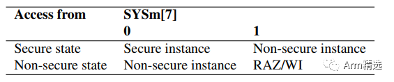
MRS and MSR instruction encoding bit[7] indicates which group of registers are being operated on (Secure or NON-Secure)
Comparison between Cortex-A TrustZone and Cortex-M TrustZone:
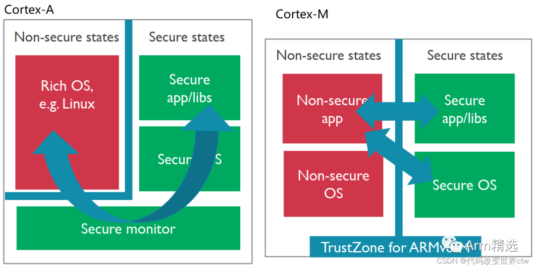
On Cortex-M, switching between dual systems uses the Secure Gateway (SG) instruction, but SG can only be called on special memory, even if NSC (non-secure callable)
5. Exception Numbers and Exception Priorities
A Nested Vectored Interrupt Controller (NVIC) interrupt controller is built into Cortex-M
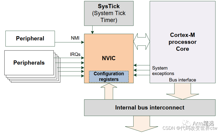
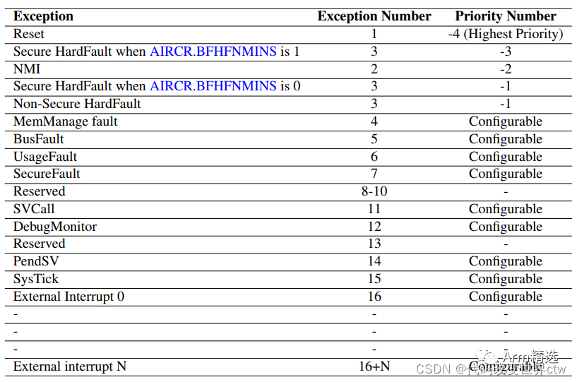
Cortex-M exceptions and interrupts have the following priorities