Invisible faults cannot escape perception. Inside the nacelle of a wind turbine, the transmission chain tirelessly converts the rotation of the wind wheel into clean electricity. This complex system, composed of the main shaft, gearbox, and generator, is known as the “heart” of the wind turbine. Once a serious fault occurs, it not only incurs huge maintenance costs and causes prolonged downtime losses but also delivers a fatal blow to the operational efficiency of the wind farm.
How can we prevent problems before they occur and accurately detect the “health risks” of the transmission chain? The answer lies in the Condition Monitoring System (CMS). Within the CMS, piezoelectric vibration sensors play a crucial role akin to a “stethoscope”.
 1Core Principle: How Does It “Hear” Faults?
The core of the piezoelectric vibration sensor is the piezoelectric effect: certain special crystalline materials (such as quartz and piezoelectric ceramics) generate an electric charge proportional to the mechanical stress applied to them. Essentially, it is a high-precision device that converts “vibration acceleration” into “electrical signals”. The workflow is clear: tiny vibrations→act on the internal piezoelectric element→generate weak charge signals→after amplification and conversion by the built-in circuit, output voltage signals that can be collected and analyzed. This signal faithfully records the amplitude, frequency, and waveform of the equipment’s vibrations, which are the key “codes” for assessing the health status of the equipment.
 2Strategic Deployment: Where Are Sensors Installed on the Transmission Chain?
The CMS system is not just about randomly installing a few sensors. The placement of piezoelectric vibration sensors on the transmission chain is a precise strategic deployment aimed at covering all high-fault areas.
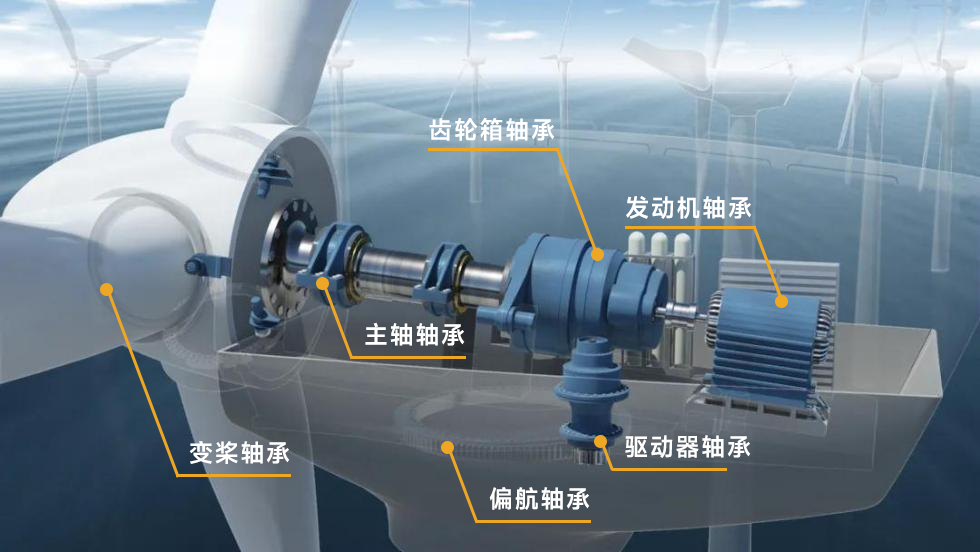
Typical installation locations for sensors in doubly-fed units include:
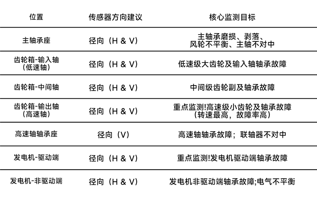
Through the deployment at these key points, the sensors form a three-dimensional, all-encompassing “monitoring net”.
 3
3
From Data to Decision: How Does It Accurately “Predict” Faults?
Collecting vibration signals is just the first step; the more critical task is to “decode” fault information through professional signal processing techniques.
1. Time Domain Analysis: Observing “Waveforms”
Observe the overall level (RMS) of the vibration waveform and its impact characteristics (peak value, kurtosis). The kurtosis index is particularly sensitive to early impulsive faults (such as bearing pitting).
2. Frequency Domain Analysis (Spectral Analysis): Listening to “Tones” as the Core Means
This is the “golden key” to fault diagnosis. Decomposing complex vibration waveforms into components of different frequencies is like breaking down a chord into individual notes. Different faults have their specific “notes” (characteristic frequencies):
Bearing Faults:Inner race, outer race, and rolling elements all have their unique characteristic frequencies.
Gear Faults:The meshing frequency of gears and their sidebands can reveal gear wear, broken teeth, or eccentricity.
Imbalance:Vibration energy concentrates at the 1x frequency of the rotational speed.
Misalignment:Vibration energy concentrates at the 2x frequency of the rotational speed.
3. Envelope Demodulation Analysis: Amplifying the “Weak Cries for Help”
For extremely weak impulsive signals generated by early bearing faults, which are submerged by other vibrations, envelope demodulation technology can extract and amplify them from background noise like a magnifying glass, thus achieving very early warning.
 4
4
ExceedingIndustry Standards:LNS® Piezoelectric Vibration Sensors’ Unique Advantages in CMS
1. Unmatched Reliability: Designed for Harsh Wind Power Environments
The nacelle of a wind turbine is an extremely harsh working environment: temperature fluctuations, grease contamination, strong electromagnetic interference, and continuous mechanical stress. LNS® sensors are designed to face these challenges.
Robust Sealing and Structure:
Laser-welded 316L stainless steel housing: provides the highest sealing level IP68, effectively resisting corrosion from grease, moisture, and salt mist, ensuring that the core piezoelectric elements remain unaffected by moisture and degradation throughout their lifecycle (the sensors can continue to operate normally after 1440 hours of salt spray testing).
Designed to last as long as the CMS: High-quality materials and manufacturing processes are aimed at achieving a design life equal to that of the wind turbine’s transmission chain, significantly reducing maintenance and replacement costs due to sensor failures.
Excellent Environmental Adaptability:
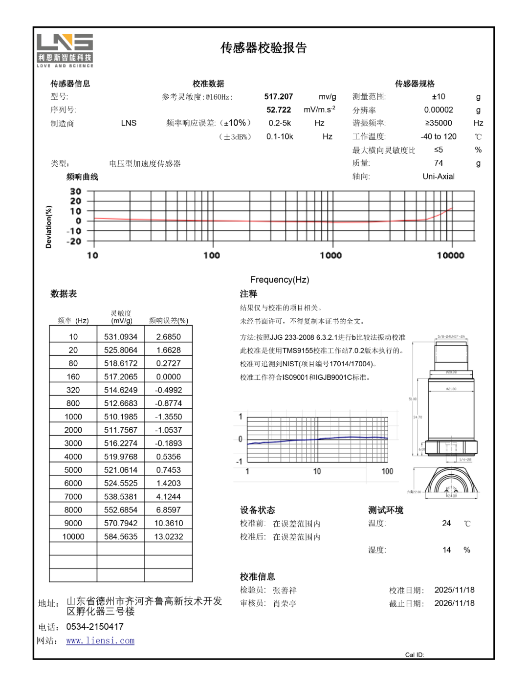
Wide operating temperature range (standard frequency -40°C to +120°C, low frequency -40°C to +120°C): ensures consistent performance and stable signal output in the severe cold of the north and the high temperatures of summer nacelles.
Outstanding electromagnetic interference resistance: The strong electromagnetic fields of generators are a significant source of interference for sensor signals. LNS® sensors typically possess excellent EMI/RFI suppression capabilities, ensuring that the output is a pure mechanical vibration signal rather than electrical noise.
2. Precise Diagnostic Performance: Capturing Fault Information from Macro to Micro
The ultimate goal of the CMS is to achieve early warning, which requires sensors not only to “hear” vibrations but also to “hear” the details clearly.
Wide Frequency Response and Dynamic Range:
LNS® sensors provide a flat frequency response range from 0.1Hz to over 15kHz (standard frequency 0.5Hz~15kHz, low frequency 0.1Hz~10kHz). This means that the same sensor can capture low-frequency vibrations of the main shaft and low-speed gears (used for diagnosing imbalance and misalignment) as well as weak high-frequency impacts from high-speed bearings and gears (used for early pitting and spalling diagnosis), achieving “multi-use” and cost optimization.
Excellent Signal-to-Noise Ratio and Sensitivity:
A high signal-to-noise ratio means that the sensor can clearly extract weak fault signals from environmental background noise. This is crucial for early fault diagnosis. LNS® sensors provide an extremely high signal-to-noise ratio through optimized internal structures and electronic designs, ensuring that weak “fault calls” are no longer drowned out.
Excellent Cross-Sensitivity Suppression:
In complex vibration fields, sensors respond not only to vibrations in the axial direction but also to lateral vibrations, known as cross-sensitivity. LNS® has reduced cross-sensitivity to a very low level (typically <3%), ensuring high fidelity and directional accuracy of measurement data, laying the foundation for precise fault localization.
3. Special Optimization for Wind Power CMS
Some models of LNS® sensors also offer features specifically tailored to the needs of wind power CMS:
Lightning Surge Protection:
Wind turbines are high-risk targets for lightning strikes. The sensors are equipped with high-level surge protection to prevent induced currents from lightning strikes from damaging the data acquisition system through the cables, enhancing the overall stability of the CMS.
High Insulation Voltage Design:
The sensor housing can withstand AC or DC voltages up to 4000V between its internal signal ground/circuit and the housing without breakdown, maintaining normal operation. In the event of equipment failure or induced voltage, it prevents high voltage from entering the backend precision data acquisition system through the sensor.
4. Long-Term Stability and Trust Value
Low Sensitivity Temperature Drift:
Over time and with changes in environmental temperature, the sensor’s output remains very stable. This ensures the comparability and reliability of long-term monitoring data trends, avoiding false alarms due to sensor drift.
Long-Term Stability:
With a delivery scale of over 150,000 units and only 9 failures, the performance is defined by near-zero defects.
Industry Validation and Trust:
The LNS® brand has established a strong quality endorsement through long-term successful applications in critical industrial sectors (not only wind power but also nuclear power, aviation, etc.).
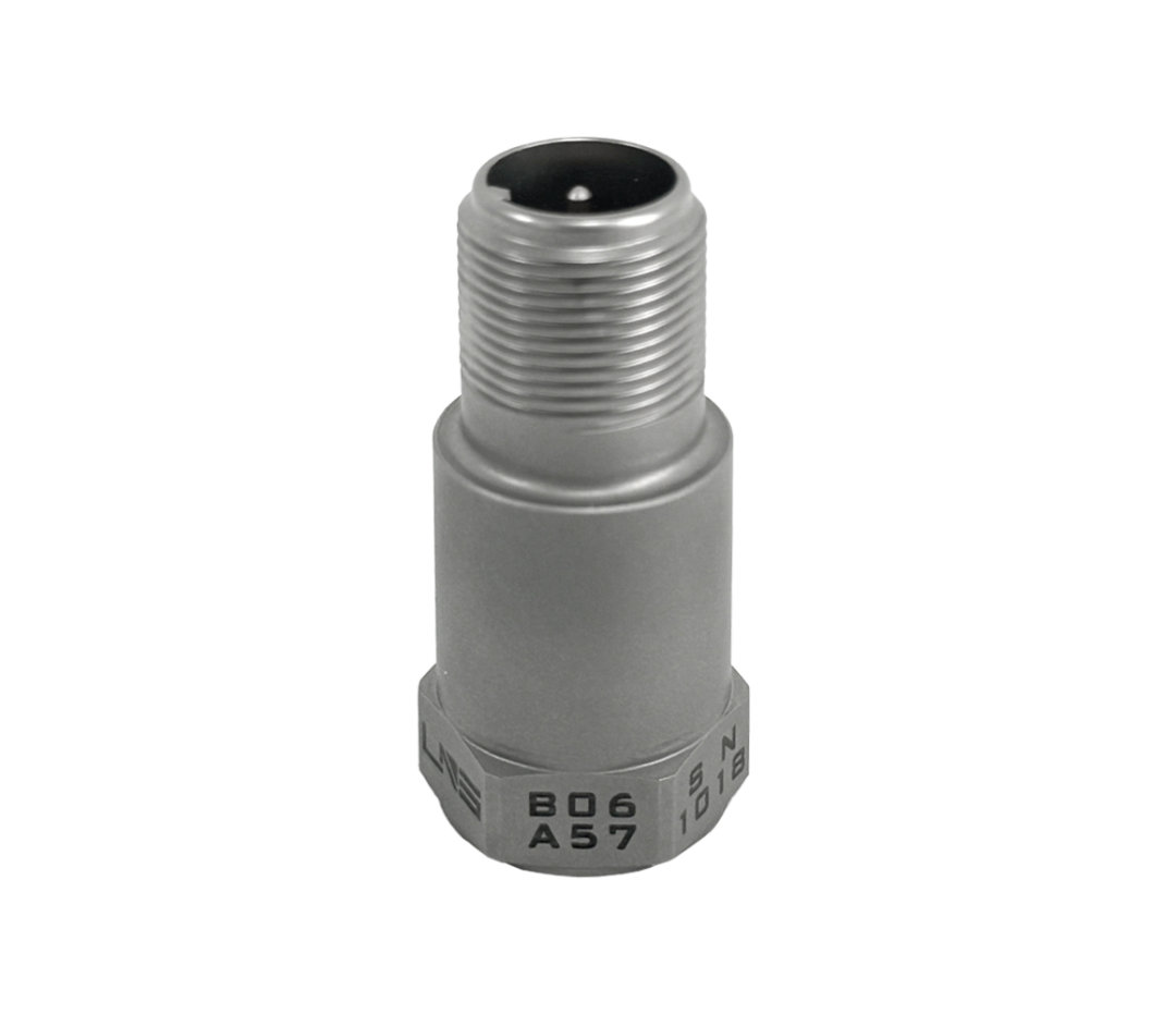
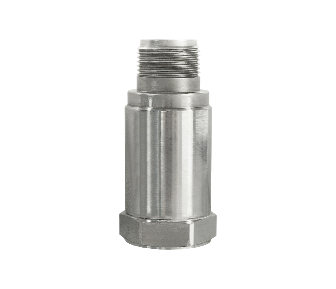
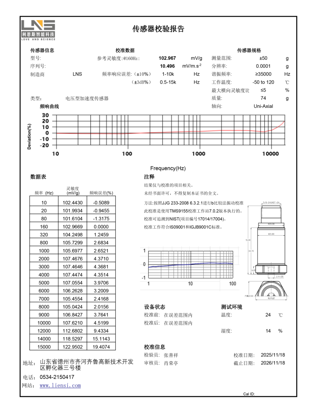
“From Passive Maintenance to Predictive Maintenance: The Intelligent Cornerstone”
Piezoelectric vibration sensors, this seemingly inconspicuous small component, are the nerve endings of modern wind power intelligent operation and maintenance systems. They make the invisible mechanical state perceivable, quantifiable, and analyzable.
With the data collected through them, wind farm operation and maintenance personnel no longer rely on “experience and luck” but can accurately predict component lifetimes, scientifically plan maintenance schedules, and maximize the reduction of unplanned downtime, truly achieving a smart leap from “repair when broken” to “prevent problems before they occur” predictive maintenance.
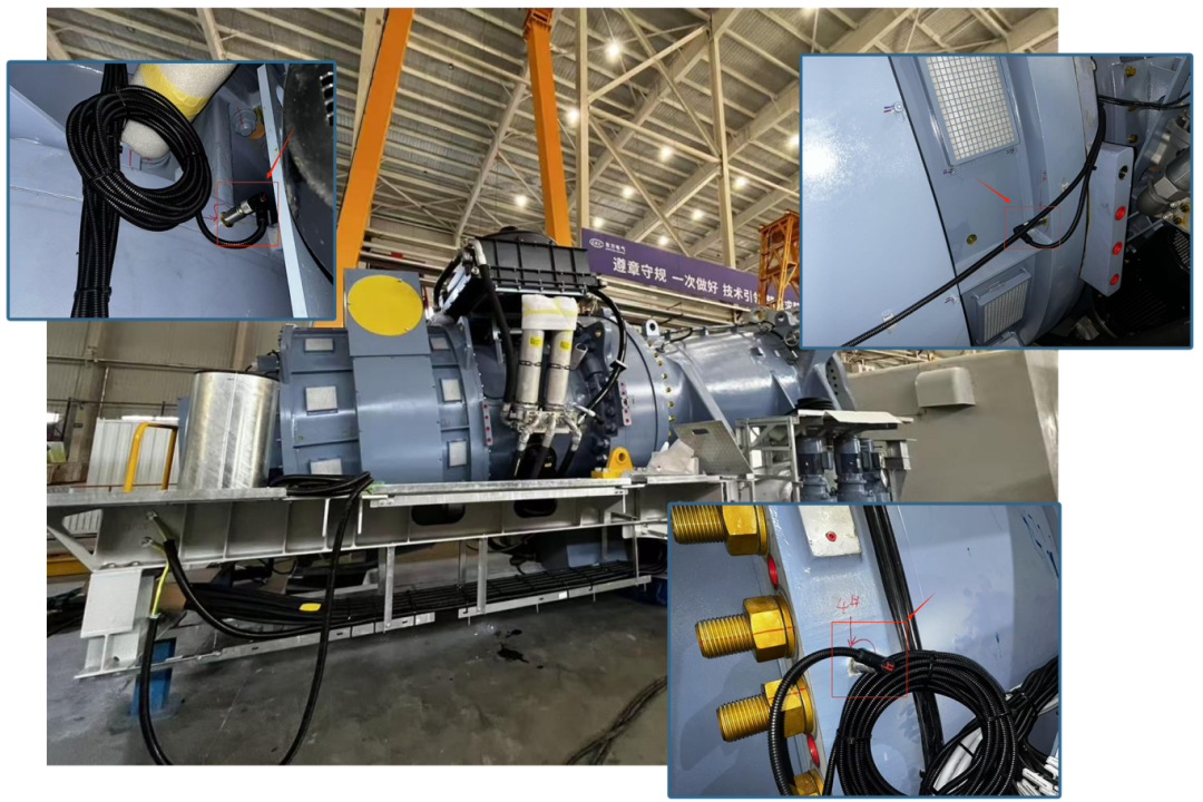
As we move towards the era of grid parity in wind power, with increasingly urgent demands for cost reduction and efficiency improvement, using CMS systems centered around LNS® piezoelectric vibration sensors is undoubtedly a key part of enhancing the core competitiveness of wind farms.