IMU (Inertial Measurement Unit) is a sensor module used to measure the acceleration and angular velocity of an object. It typically consists of multiple sensors and is a core component for achieving attitude estimation, navigation, and motion control in fields such as robotics, drones, autonomous driving, smartphones, virtual reality (VR), and aerospace.
1. Basic Components of IMU
A typical IMU contains at least the following two types of sensors:
1. Accelerometer
- Measurement: Three-axis linear acceleration (X, Y, Z directions)
- Unit: m/s² or g (gravitational acceleration, 1g ≈ 9.8 m/s²)
- Function
- Detects linear motion of the object (e.g., moving forward, backward, up, down)
- Measures the direction of gravity for estimating pitch and roll angles
- Determines whether the object is at rest or in free fall
Note: The accelerometer cannot distinguish between “motion acceleration” and “gravitational acceleration,” so attitude calculations during dynamic motion may be interfered with.
2. Gyroscope
- Measurement: Three-axis angular velocity (the speed of rotation around the X, Y, Z axes)
- Unit: °/s or rad/s
- Function
- Measures the rotational motion of the object (e.g., yaw, pitch, roll)
- Provides high-frequency attitude change information, with a quick response
- Used to calculate the rate of change of attitude angles
Disadvantage: There is drift, and long-term integration can lead to accumulated angular errors.
(Optional) 3. Magnetometer
- Measurement: Three-axis magnetic field strength
- Unit: μT (microtesla)
- Function
- Provides an absolute heading reference (similar to a compass)
- Used to correct the yaw drift of the gyroscope
- Helps determine the device’s direction relative to the Earth’s magnetic north
IMUs that include a magnetometer are sometimes referred to as 9-axis IMUs (3 accelerometers + 3 gyroscopes + 3 magnetometers)
2. Main Parameters Provided by IMU
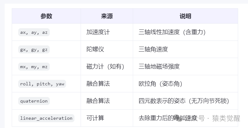
Note: The raw IMU generally only outputs <span>ax, ay, az, gx, gy, gz</span>, while <span>attitude angles</span> and <span>quaternions</span> are calculated through sensor fusion algorithms (such as complementary filtering, Kalman filtering, Madgwick, Mahony).
3. Core Functions of IMU
1. Attitude Estimation
- Real-time calculation of the device’s three-dimensional attitude (pitch, roll, yaw)
- Applied in drone stabilization, robot balance control, automatic screen rotation in smartphones, etc.
2. Inertial Navigation
- Obtains velocity by integrating acceleration, then integrates to get displacement
- Provides short-term positioning capability when GPS signals are lost (e.g., in tunnels, indoors)
- Often used in conjunction with GPS, vision, and LiDAR (e.g., INS/GPS integrated navigation)
3. Motion Detection and Behavior Recognition
- Detects vibrations, impacts, free falls, gait, etc.
- Used in smartwatches for step counting, fall detection, device wake-up, etc.
4. Stabilization and Control
- Provides feedback signals for aircraft, camera gimbals, robotic arms, etc., to achieve closed-loop control
- For example: Drones adjust motor speeds based on IMU data to maintain level flight
5. Foundation for Sensor Fusion
- IMU data has a high update frequency (up to 1000Hz), which can compensate for the shortcomings of low-frequency sensors like GPS (1-10Hz) and vision (10-30Hz)
- In SLAM (Simultaneous Localization and Mapping) systems, IMU provides motion prediction, enhancing system robustness and accuracy (e.g., VIO, LIO)