For embedded developers, the MCU acts like a tireless little steward, responsible for directing electronic devices to complete various tasks. But have you ever thought about how this “little steward” is awakened from a completely “asleep” state to gradually enter a working state the moment you power on the device? The startup process behind this is the foundation of MCU operation and is key to troubleshooting hardware faults and optimizing programs. Before discussing the startup process, we must first understand the state of the MCU when it is “powered off”. Just like a phone that shuts down when the battery is dead, the CPU, memory, and sensors are all in an “offline” state. When the MCU is powered off: the core CPU (Central Processing Unit) stops working, and all data in the registers is lost; RAM (Random Access Memory) is like a blackboard without power, with all its contents (temporary data) cleared; Flash (Flash memory) retains the programs we have written, but it is “passive storage” and does not actively “wake up” the MCU; peripherals (such as serial ports, ADCs, timers) are also in a default “off” or “initial chaos” state, unable to respond to any commands. In simple terms, a powered-off MCU is like a factory “filled with materials (programs in Flash) but without anyone directing it, and all equipment is idle”. The “startup process” is the entire procedure from “waking up the manager (CPU)” to “turning on the machines (peripherals)”, “retrieving the production plan (loading the program)”, and finally allowing the factory to operate normally. When you plug in the power supply to the circuit board or press the reset button, the startup process begins, and this step is called “power-on reset”.
1. Reset Circuit
Every MCU has a “reset circuit” inside, which functions like an alarm clock. When the power supply voltage reaches the minimum value at which the MCU can operate (for example, the threshold for a 3.3V MCU might be 2.8V), the reset circuit sends a “reset signal” to the CPU (usually a low or high pulse). Why is a reset circuit necessary? Because the voltage is not instantly stable when the power is turned on; it may fluctuate (for example, rising slowly from 0V to 3.3V). If the CPU is awakened before the voltage stabilizes, it may become “confused” and execute incorrect instructions. The reset circuit waits until the voltage stabilizes before sending the reset signal. Some MCUs also support “manual reset” (such as a reset button), which works on the same principle as power-on reset: when the button is pressed, the reset circuit sends a reset signal again, allowing the MCU to “wake up” again, equivalent to a “restart”.
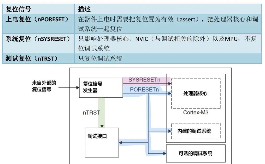
2. The “First Second” After Reset
When the CPU receives the reset signal, it first does one thing: it restores its “working environment” to the “factory default state”. For example: clearing all registers (such as the program counter PC and stack pointer SP), making the CPU forget its previous “memories”; setting the program counter PC (equivalent to the “address of the instruction to be executed”) to a “default value”. This value is the “starting address” of the startup process, and different manufacturers have different starting addresses for their MCUs; for example, the starting address for STM32 is 0x00000000, while for the 51 microcontroller it is 0x0000; all peripheral interrupts are disabled (to avoid being “disturbed” by peripherals right after waking up), retaining only the core functions related to reset. 3. Step Two: Boot Mode Selection After the CPU is reset, it knows that “it needs to start executing instructions”, but it does not yet know “where the instructions are stored”—are they in internal Flash? Or on an external SD card? Or a temporary program downloaded via serial? This requires “boot mode selection” to determine. 1. Boot Mode The MCU’s “boot mode” essentially selects the “location of the program storage” (professionally called “program memory”). There are three common boot modes: Flash boot mode: reads the program from the MCU’s internal Flash (the most commonly used mode, where our written programs are usually burned); RAM boot mode: reads the program from RAM (generally used for debugging, such as temporarily loading the program into RAM for execution, which will disappear after power off); Peripheral boot mode: reads the program from external devices (such as loading programs from serial, USB, or SD card, used for mass production or remote upgrades). Why is it necessary to select a boot mode? For example, when developing a product, you need to debug the program in RAM first (after modifying the code, you can load it directly into RAM without burning it, saving time); during mass production, switch to Flash mode (the program exists in Flash and is not lost when powered off); if remote upgrades are needed, use peripheral boot mode (receiving new programs from the network and writing them into Flash). 2. How to Select Boot Mode? The boot mode is not set by software but is determined by the voltage levels of “hardware pins”. For example, the boot mode of STM32 is determined by the high and low levels of the BOOT0 and BOOT1 pins: when BOOT0=0 and BOOT1=0, it starts from internal Flash; when BOOT0=1 and BOOT1=0, it starts from system memory (used for serial program downloads); when BOOT0=1 and BOOT1=1, it starts from RAM.
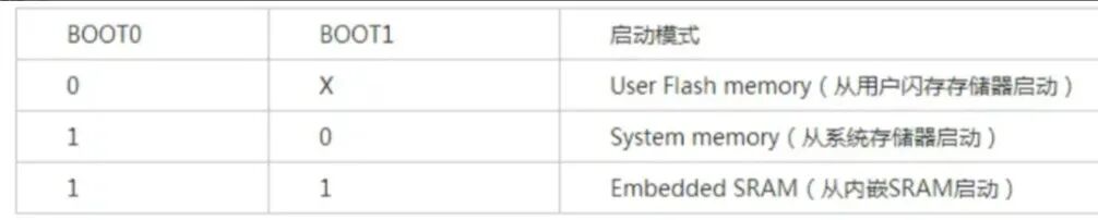
These pins are detected by internal circuits when the MCU is powered on, and the CPU determines “from which address to start reading the program” based on the detected levels.
4. Step Three: Load the Vector Table After determining the boot mode, the CPU will go to the corresponding memory (such as Flash) to read the first critical data, the vector table, from the “starting address” (for example, 0x00000000). 1. What is the Vector Table? The vector table is essentially a “list of addresses” that records the entry addresses of all “key functions” of the MCU. The two core addresses are: the initial value of the stack pointer (SP): a specific area in RAM is allocated as the “stack area” for storing temporary data (such as function parameters and local variables). The first data in the vector table is the “highest address” of the stack area (the stack top), and the CPU will first write this address into the stack pointer SP, which is equivalent to “defining the storage area for temporary data”; the address of the reset interrupt service routine: the second data in the vector table is the entry address of the “reset interrupt service routine”. After the CPU reads this address, it will jump to this program for execution.
In addition to these two, the vector table also contains addresses for other interrupt service routines (such as serial interrupts, timer interrupts, ADC interrupts), but only the “reset interrupt service routine” is used during the startup phase. You can think of the vector table as the “map” that the CPU holds when it just wakes up, indicating “where the temporary items storage area (stack area) is” and “which office (reset interrupt service routine) to report to next”. 2. Why Should the Vector Table Be at the Starting Address? Because after the CPU is reset, the default value of the program counter PC is the starting address (for example, 0x00000000), and it will first read the data at this address. If the vector table is not at the starting address, the CPU will not be able to find the “stack top address” and the “reset interrupt program address”, causing the startup process to get stuck. Some MCUs support “vector table remapping” (such as STM32), which allows the vector table to be moved from the starting address to another location (such as another area of RAM or Flash), but this is an operation after startup; during the startup phase, the vector table must be at the starting address. 5. Step Four: Execute the Reset Interrupt Service Routine After the CPU jumps to the “reset interrupt service routine”, it finally begins to execute specific code. Is this program written by us? Not entirely. Most of it is code from the “startup file” provided by the MCU manufacturer, which we can also modify according to our needs. Its core task is to “initialize hardware” to prepare for the subsequent execution of user programs. 1. Initialize RAM RAM is a “temporary warehouse”; data will be lost after power off, and when powered on, it contains “garbage” (random data). The reset interrupt service routine will first do one thing: initialize RAM, including: copying “initialized global variables” from Flash to RAM: global variables defined in our programs with initial values (for example, int a=10) are stored in Flash with the program. During startup, they need to be copied to RAM (because accessing RAM is faster than accessing Flash, and global variables need to be modifiable); zeroing out “uninitialized global variables”: if global variables are not assigned initial values (for example, int b), the program will clear the RAM area they occupy to avoid random values when used later. This step is like cleaning up the “temporary warehouse” before going to work, moving the necessary items (initialized global variables) from the “long-term warehouse (Flash)” to the “temporary warehouse (RAM)”. 2. Initialize the Stack The CPU has already obtained the stack top address from the vector table, but it also needs to initialize the “heap area” (if dynamic memory allocation is used, such as the malloc function). The stack area is used for storing function parameters and local variables, while the heap area is used for storing dynamically allocated memory (such as temporarily created data during program execution). The reset interrupt service routine will set the starting address and size of the heap area to ensure that when subsequent programs call functions or request dynamic memory, there is a place to store data. If the stack initialization is incorrect (for example, if the stack area is too small), a “stack overflow” will occur during program execution, causing the MCU to crash. 3. Initialize the Clock The CPU of the MCU and peripherals (such as serial ports, timers, etc.) require a “clock signal” to work, just like a mechanical watch needs winding to function. After reset, the MCU’s clock defaults to the “internal low-speed clock” (for example, the HSI clock of STM32, with a frequency of 8MHz), which is suitable for simple operations during the startup phase but not for high-performance tasks (such as high-speed serial communication or ADC sampling). The reset interrupt service routine will “switch the clock”: enabling the external high-speed clock (for example, the HSE clock of STM32, with a frequency of 25MHz), and then through the “clock tree” (the internal clock distribution circuit of the MCU), increase the clock frequency of the CPU and peripherals to the rated value (for example, the maximum CPU clock of STM32F103 is 72MHz). 4. Initialize Key Peripherals Depending on the requirements, the reset interrupt service routine will also initialize some “peripherals that must be used during the startup phase”. For example: if the program needs to print startup information via serial, it will initialize the serial port’s baud rate, data bits, and stop bits; if it needs to detect external sensors, it will initialize the ADC or I2C interface; if it needs to prevent the program from running away, it will initialize the watchdog (WatchDog). If the program gets stuck, the watchdog will trigger a reset, allowing the MCU to restart. The initialization of these peripherals is not mandatory and depends on your application scenario. For example, a simple LED blinking program may only need to initialize GPIO (General Purpose Input/Output) and not require serial initialization. 5. Jump to the User Main Program After all initialization work is completed, the reset interrupt service routine will execute the last instruction: jump to the main function of the user program. This step marks the “end of the startup process”, and the MCU officially enters the “working state”, beginning to execute the code you have written (such as controlling LED blinking, reading sensor data, communicating with a mobile phone, etc.). From here on, the CPU runs entirely according to your instructions. The startup process is like “power-on self-test + environment preparation”, and the main function is the beginning of the “official work”. 6. Step Five: “Follow-up Work” After Startup Although the startup process has ended, the MCU still needs to handle some “subsequent issues” to ensure stable operation. 1. Interrupt Enable During the startup phase, to avoid interference, the CPU will disable all peripheral interrupts. After entering the main function, you need to “enable interrupts” based on your needs, such as allowing interrupts to be triggered when serial data is received, when the timer reaches a certain time, or when ADC sampling is completed. Interrupts act like “call bells for peripherals”: when a peripheral needs the CPU to process data, it will trigger an interrupt, causing the CPU to pause the currently executing code and jump to the “interrupt service routine” to handle the peripheral’s request, then return to the original code to continue execution. If interrupts are not enabled, the CPU can only “poll” the peripherals (constantly asking “do you have data to process”), which is very inefficient. 2. Watchdog Initialization If a bug occurs during program execution (such as an infinite loop or array out-of-bounds), the MCU will get stuck and cannot continue working. The watchdog is designed to solve this problem: after startup, the watchdog is initialized, and the program must “feed the watchdog” (send a signal) within a “specified time”; if the program gets stuck and does not feed the watchdog in time, the watchdog will trigger a reset, allowing the MCU to restart and resume normal operation. The watchdog is not a mandatory step in the startup process, but it is an essential “safety measure” for scenarios requiring high stability, such as industrial control and automotive electronics. 3. Low Power Optimization: If your device is powered by a battery (such as a smart bracelet or sensor node), after startup, you also need to configure a “low power mode”. The MCU supports various low power modes (such as sleep mode, stop mode, standby mode), which, when not needed (for example, while waiting for sensor data), enter low power mode, turning off some clocks and peripherals to reduce power consumption and extend battery life. Low power configuration is usually completed in the main function, triggered according to the program’s running logic (for example, waking up every 10 seconds, collecting data, and then entering low power mode). 8. Summary of the Core Logic of the MCU Startup Process 1. Hardware Trigger Stage: Power on → Reset circuit detects voltage → Sends reset signal to CPU → CPU restores to default state; 2. Mode Selection and Boot Stage: CPU detects boot mode pins → Determines program memory → Reads vector table → Jumps to reset interrupt service routine; 3. Software Initialization Stage: Initializes RAM, stack, clock, key peripherals → Jumps to main function → Executes user program.