1. The Role of Rotary Variable Transformers
A rotary transformer, also known as a rotary variable transformer or angle sensor, is a type of position sensor that can accurately detect the position, direction, and speed of a rotor. It is used to control the direction and speed of drive motors or generators (for energy recovery).

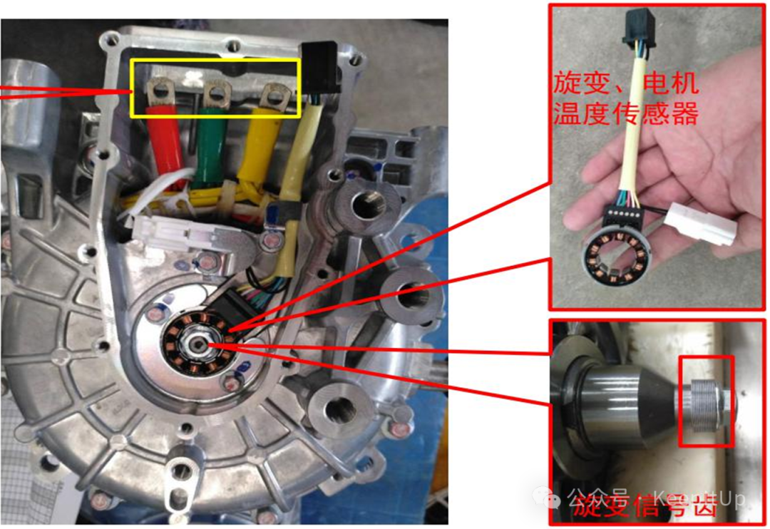
2. Structure of the Rotary Variable Transformer
The working principle of a rotary variable transformer is similar to that of a transformer that can rotate. It mainly consists of two parts:
1. Stator: Fixed to the motor housing, it contains two sets of mutually perpendicular coils: the excitation winding and the sine/cosine output windings.
2. Rotor: Mounted on the motor shaft, it rotates with the motor and has a special pole structure or excitation winding.
3. Working Principle of the Rotary Variable Transformer
1. Excitation Signal: The motor controller sends a high-frequency sine wave AC signal (e.g., 10kHz) to the stator excitation winding through the rotary decoder chip.
2. Electromagnetic Coupling: This high-frequency signal is coupled to the rotor through electromagnetic induction. Since the rotor has a pole structure, its shape modulates this signal.
3. Signal Modulation and Output: As the rotor rotates, the modulated signal is transmitted back to the stator’s sine winding and cosine winding. The amplitudes of the signals output from these two windings are proportional to the sine (Sin) and cosine (Cos) values of the rotor angle θ.
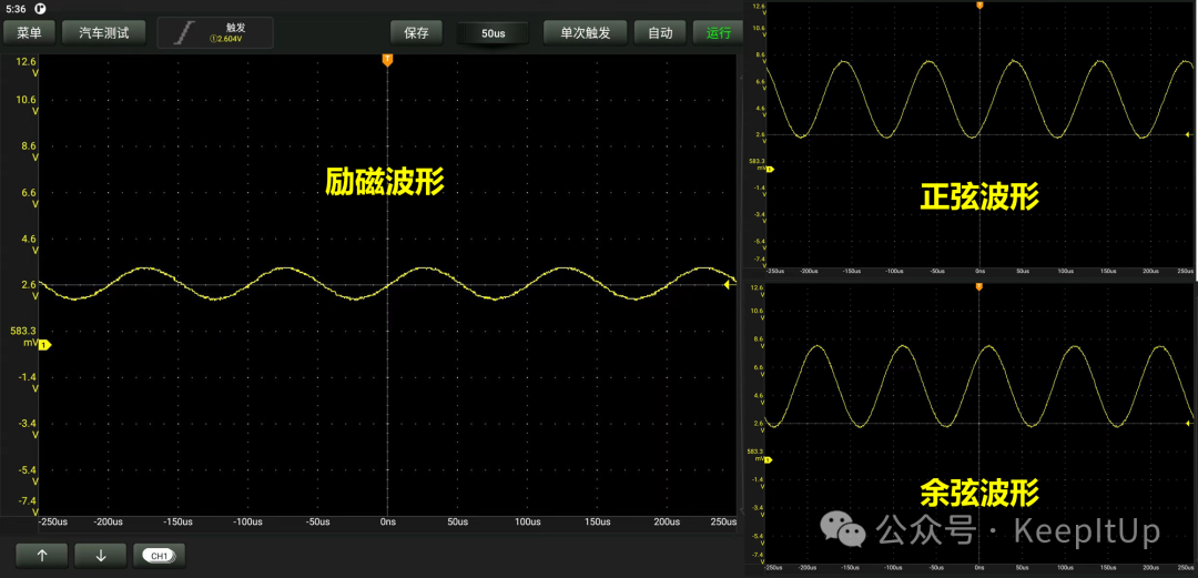
4. In simple terms, it recognizes the signal through waveform recognition. (This waveform serves as a reference.)
4. Maintenance Methods for Rotary Variable Transformers
The rotary variable transformer itself is made up of three sets of coils, so the resistance method is the most basic judgment.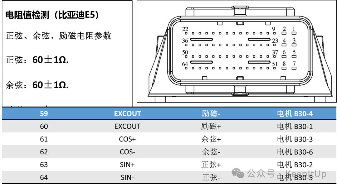
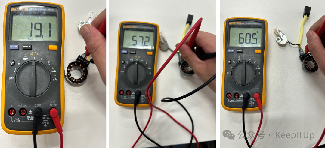 The standard values need to be looked up in the maintenance manual and online resources. The empirical method R sine ≈R cosine R excitation ≈1/2R sine ≈1/2R cosine. Below are two maintenance cases. Case 1: The resistance of the rotary variable transformer is normal.
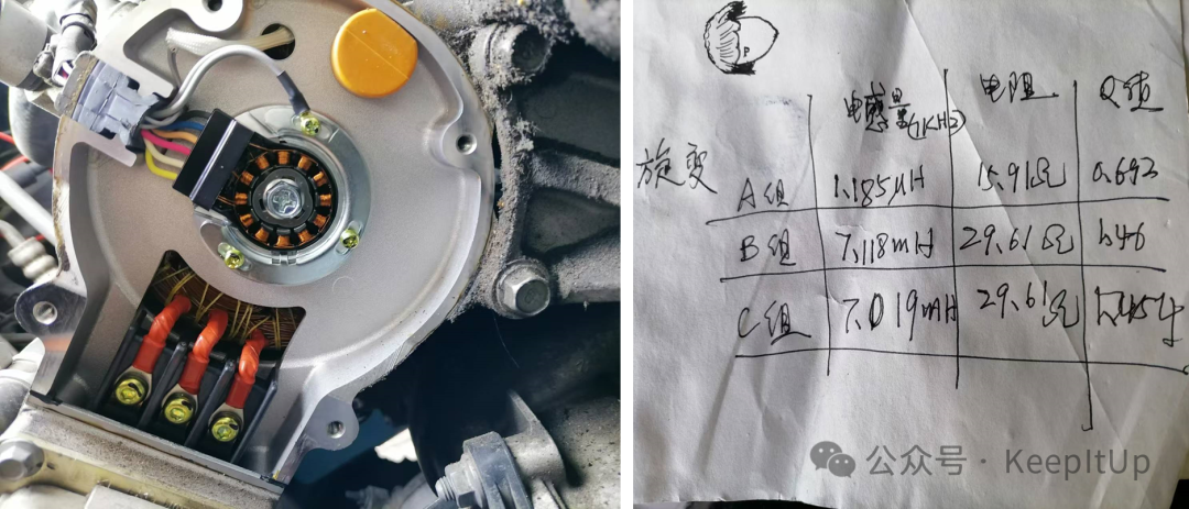 Case 2: The resistance of the rotary variable transformer is abnormal.
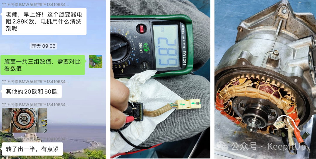
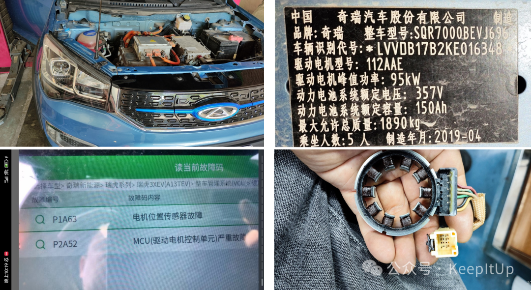
 5. Common Fault Codes for Rotary Variable Transformers
 The main points of maintenance are the rotary variable transformer itself and the signal circuit. Additionally, when replacing this sensor, zero position calibration must be performed; otherwise, abnormal vehicle operation may occur.
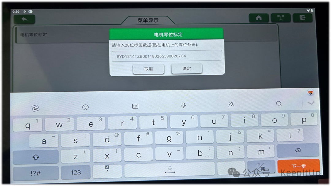 For those who do not know how to perform zero position calibration, please refer to the video explanation below: