1. I2C Protocol
I2C (Inter-Integrated Circuit) is a serial communication bus, known in Chinese as the integrated circuit bus. It uses a multi-master/slave architecture and was designed by Philips in the early 1980s.
Each device on the I2C bus can act as a master or a slave, but typically there is only one master device on the bus, which can support multiple slave devices. The master device is generally responsible for generating the clock signal (providing the clock signal to the slave devices) and initializing the data output on the bus. Therefore, the master device is usually the CPU, while the slave devices can only passively respond to communication requests initiated by the master device. Various I2C interface chips will act as slave devices. I2C can have multiple slave devices, and the master device needs to determine which slave device to communicate with using addresses.
I2C devices have read addresses, write addresses, and device addresses.
The write address of an I2C device: I2C device address << 1
The read address of an I2C device: (I2C device address << 1) + 1
2. Characteristics of I2C
1. There is one clock line, so it is synchronous communication;
2. There is only one data bus, so data is transmitted serially;
3. This bus supports bidirectional transmission but is time-division multiplexed, so it is half-duplex communication.
3. I2C Modes
The I2C bus is a synchronous, half-duplex serial bus that uses level signals for transmission, supporting the following speeds:
Standard mode: up to 100 kbit/s
Fast mode: up to 400 kbit/s
Fast mode+: up to 1 Mbit/s
High-speed mode: up to 3.4 Mbit/s
Ultra-fast mode: up to 5 Mbit/s
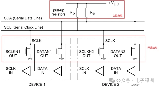
Architecture diagram of I2C:
4. Why Open-Drain Output?
The I2C protocol supports multiple master devices and multiple slave devices on a single bus. If push-pull output is used instead of open-drain output, it could lead to short circuits between master devices. Therefore, the bus typically uses open-drain output (which does not require level shifting).
In other words, if designed as push-pull output, it could causeshort circuits, as shown in the diagram below:
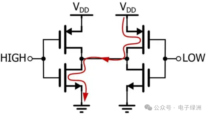
When two slave devices pull one high and the other low, it can cause a short circuit. However, with open-drain output, the current is limited by a pull-up resistor, preventing short circuits.
The second reason is that arbitration for multi-device communication requireswire and logic. Open-drain output can achieve this, while using push-pull output for wire and logic would lead to the aforementioned short circuit.
Wire and logic: When the master device wants to set the bus to 1 and is idle, if a slave device outputs 0 at that time, it will result in 1&0=0, causing the master device to think the bus is still occupied and cannot be idle. The master device will give up pulling high, thus not disrupting the data being communicated by the slave device.
5. Why Use Pull-Up Resistors?
Pull-up resistors are necessary because I2C communication requires the ability to output a high level. Generally, open-drain outputs cannot output a high level, but if a pull-up resistor is connected to the drain, level shifting can be achieved.
I2C consists of two buses, SDA and SCL. The output stage of devices connected to the bus must be open-drain, all connected to the power supply through pull-up resistors, enabling the “wire and” function.When the bus is idle, both lines are at a high level.
6. How to Determine the Value of Pull-Up Resistors?
The driving capability of general IO ports is in the range of2mA to 4mA.
1. The resistance value cannot be too small.
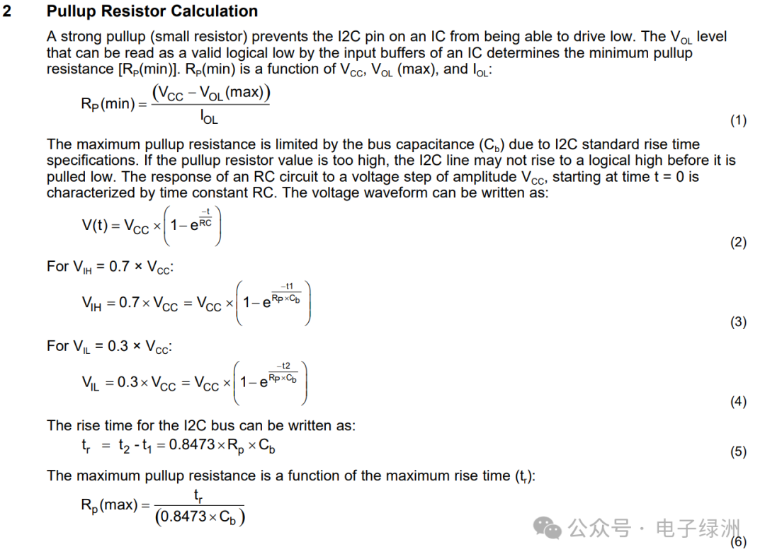
If the pull-up resistance value is too small, the current flowing into the port from VDD will be large, resulting in high power consumption, which will increase the low-level output value of the port (the I2C protocol specifies that the maximum allowed low-level output value is 0.4V).
For example, when VDD=3.3V, the current flowing in should not exceed 3mA. Using Kirchhoff’s Voltage Law (KVL):
Rmin=(VDD-0.4)/IOL=(3.3V-0.4V)/3mA=1.06K
Therefore, the pull-up resistor should typically be selected to be no less than 1K.
2. The resistance value cannot be too large.
This depends on the RC delay formed by the pull-up resistor and the capacitance on the line. The larger the RC delay, the more the waveform deviates from a square wave towards a sine wave, reducing the probability of correct data read/write. Therefore, the pull-up resistor cannot be too large.
The load capacitance on the I2C bus should not exceed 400pF. As the number of devices on the I2C bus increases, the bus load capacitance also increases accordingly. When the total load capacitance exceeds 400pF, reliable operation cannot be guaranteed. This is also a limitation of I2C.
It is recommended to use pull-up resistors of 1.5K, 2.2K, or 4.7K.
The formula for calculating the size of pull-up resistors can be found in the TI official manual:
7. I2C Clock Stretching
I2C clock stretching allows a slave device to pull the SCL line low, actively pausing the bus clock and letting the master wait until it is ready to continue communication.
Process:
The master generates the SCL clock;
The slave realizes it does not have enough time to prepare data (or needs more time);
The slave forces SCL low (open-drain output low);
The master detects that SCL is still low, so it does not send the next clock edge, pausing the bus;
Once the slave is ready, it releases SCL (pulls high), and the master continues the clock, resuming communication.
8. Timing
Timing:
Idle level: SCL and SDA are both high;
Start signal: When SCL is high, SDA is pulled low;
Stop signal: When SCL is high, SDA is pulled high;
ACK response signal: At the 9th clock, SDA is low;
NACK non-response signal: At the 9th clock, SDA is high;
——END——
In the jungle society, tears are never believed; no amount of complaints will help, and no one will pity you.
Recommended Reading
Analysis of BVDSS of MOSFETs: Key Parameters and Applications
Detailed Explanation of DC-DC BUCK Bootstrap Circuit
CMW Line Loss Calibration Tutorial: Step-by-Step Analysis to Help You Operate Accurately
TBW Lifespan of eMMC: How Much Do You Know?
[2025 Latest] Must-Review Questions for Hardware Engineer Interviews! High-Frequency Exam Points + Classic Question Analysis (Part 1)
Due to changes in the public account’s push rules, to prevent losing track of me, please like and preferably add me to your favorites. (Method: Go to the public account homepage, click the upper right corner “…”, then click to add to favorites, thank you for your support!)
Like, Share, and RevisitThank you for your “three supports”Limited-time free scan to join the group, exchange more technical and industry information