Wu Jianying Microcontroller Development Board Address
Store:
【Wu Jianying’s Shop】
Address:
【https://item.taobao.com/item.htm?_u=ukgdp5a7629&id=524088004171】

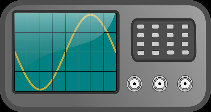
The oscilloscope is an essential instrument in modern home appliance repair. With it, technicians can quickly and accurately locate faults, so mastering the correct and proficient use of an oscilloscope is a required course for appliance repair technicians.
Although there are many brands, models, and types of oscilloscopes, their basic components and functions are quite similar. This article introduces the usage of general-purpose oscilloscopes.
I. Panel Introduction
1. Brightness and Focus Knobs
The brightness adjustment knob is used to adjust the brightness of the trace (some oscilloscopes refer to it as “luminance”). When in use, the brightness should be appropriate; if too bright, it may damage the cathode ray tube. The focus adjustment knob is used to adjust the sharpness of the trace; it should be set for the clearest image.
2. Signal Input Channels
Common oscilloscopes are often dual-trace oscilloscopes, with two input channels, namely Channel 1 (ch1) and Channel 2 (ch2). Probes can be connected to these channels, and the oscilloscope casing should be grounded. The probes are then inserted into the points to be measured.
3. Channel Selection Keys (Vertical Mode Selection)
Common oscilloscopes have five channel selection keys:
(1) ch1: displays Channel 1 alone;
(2) ch2: displays Channel 2 alone;
(3) alt: alternates between the two channels;
(4) chop: displays the two channels intermittently, used for slow scan speeds in dual-trace display;
(5) add: adds the signals from both channels. In repairs, Channel 1 or Channel 2 is usually selected.
4. Vertical Sensitivity Adjustment Knob
This knob adjusts the vertical deflection sensitivity. It should be set according to the amplitude of the input signal. The value indicated by this knob (e.g., 0.5v/div, meaning each division in the vertical direction represents 0.5v) is multiplied by the number of divisions the measured signal occupies on the screen to obtain the amplitude of the measured signal.
5. Vertical Position Adjustment Knob
This knob is used to adjust the position of the measured signal trace in the vertical direction on the screen.
6. Horizontal Scan Adjustment Knob
This knob adjusts the horizontal speed. It should be set according to the frequency of the input signal. The value indicated by this knob (e.g., 0.5ms/div, meaning each division in the horizontal direction represents 0.5ms) is multiplied by the number of divisions occupied by one cycle of the measured signal to obtain the period of the signal, which can also be converted to frequency.
7. Horizontal Position Adjustment Knob
This knob is used to adjust the position of the measured signal trace in the horizontal direction on the screen.
8. Trigger Mode Selection
Oscilloscopes typically have four trigger modes:
(1) Normal (norm): No display on the screen when there is no signal; when there is a signal, it displays a stable waveform in conjunction with level control;
(2) Auto (auto): Displays a trace on the screen when there is no signal; when there is a signal, it displays a stable waveform in conjunction with level control;
(3) TV Field (tv): Used to display television field signals;
(4) Peak-to-Peak Auto (p-p auto): Displays a trace on the screen when there is no signal; when there is a signal, it can obtain a stable waveform display without adjusting the level. This mode is only used in some oscilloscopes (e.g., Caltek CA8000 series oscilloscopes).
9. Trigger Source Selection
Oscilloscope trigger sources can be internal or external. If an external trigger source is selected, the trigger signal should be input from the external trigger source input terminal, which is rarely used in appliance repair. If an internal trigger source is selected, it is generally chosen from Channel 1 (ch1) or Channel 2 (ch2), and should be based on the input signal channel selection. If the input signal channel is set to Channel 1, the internal trigger source should also be set to Channel 1.
II. Measurement Methods
1. Measurement Methods for Amplitude and Frequency (using the oscilloscope’s calibration signal as an example)
(1) Insert the oscilloscope probe into the Channel 1 socket and set the probe’s attenuation to the “1” position;
(2) Set the channel selection to ch1 and the coupling mode to DC;
(3) Insert the probe tip into the calibration signal source hole; at this point, a trace should appear on the oscilloscope screen;
(4) Adjust the vertical and horizontal knobs to stabilize the waveform displayed on the screen, and set the vertical and horizontal fine-tuning to the calibration position;
(5) Read the number of divisions occupied by the waveform in the vertical direction, and multiply it by the value indicated by the vertical attenuation knob to obtain the amplitude of the calibration signal;
(6) Read the number of divisions occupied by one cycle of the waveform in the horizontal direction, and multiply it by the value indicated by the horizontal scan knob to obtain the period of the calibration signal (the reciprocal of the period is the frequency);
(7) Generally, the frequency of the calibration signal is 1kHz, and the amplitude is 0.5V, used to calibrate the frequency of the oscilloscope’s internal scanning oscillator. If it is not normal, the corresponding potentiometer inside the oscilloscope should be adjusted until it matches.
2. Example of Oscilloscope Application (measuring the 13MHz clock pulse of the 788 mobile phone)
The normal 13MHz clock signal in a mobile phone is a necessary condition for powering on, so it is often measured during repairs. The steps are as follows:
(1) Turn on the oscilloscope, adjust the brightness and focus knobs to display a moderately bright and well-focused horizontal line on the screen;
(2) Calibrate the oscilloscope as described above, then set the coupling mode to AC;
(3) Clip the ground clip of the oscilloscope probe to the ground point on the mobile phone circuit board, and insert the probe into the CPU pin of the 788 mobile phone;
(4) Power on the mobile phone and press the power button, adjusting the vertical and horizontal scan knobs to observe whether a stable waveform appears on the screen. If not, it generally indicates that there is no 13MHz signal.
For those who like this article, please give it a thumbs up!

|
Technology comes from accumulation, success comes from persistence —— Microcontroller Expert Wu Jianying |