① Click the blue text above “Wiring World“
② Click the top right corner to pin the public account

The in-vehicle network system refers to the automotive onboard computer network system formed by multiple processors connected, coordinated, and sharing information within a vehicle. In the late 1980s, BOSCH and INTEL developed the Controller Area Network (CAN) specification for automotive electrical systems. Due to the rapid development of integrated circuit technology and electronic component manufacturing technology, the price of using microcontrollers as bus interface ends gradually decreased, and bus technology entered the practical stage. With the development of automotive electronic technology, a new protocol called TTP was proposed in Europe for control systems, and as the demand for network transmission information volume in automotive information systems increased, multimedia systems’ D2B protocol and MOST protocol standards emerged. Today, in-vehicle network technology has been applied to vehicles produced by automotive manufacturers worldwide.
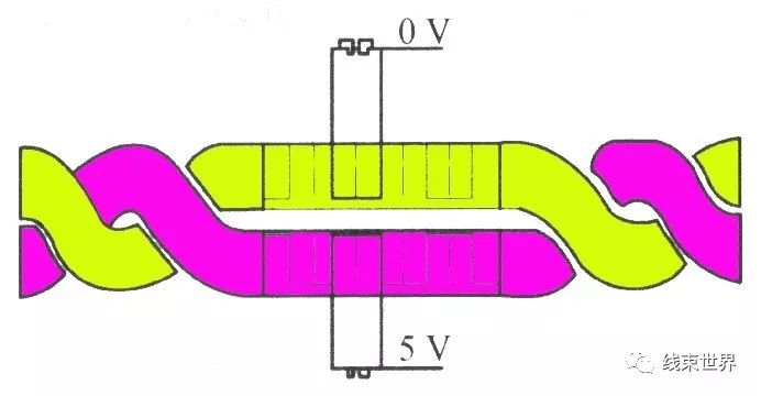
The data bus refers to the channel for running data between modules, where modules can send and receive data. The data bus is a bidirectional data bus, known as the information highway. As shown in Figure 1, the information highway in a car is actually a single or double wire twisted together to combat electronic interference (Figure 2).
Figure1
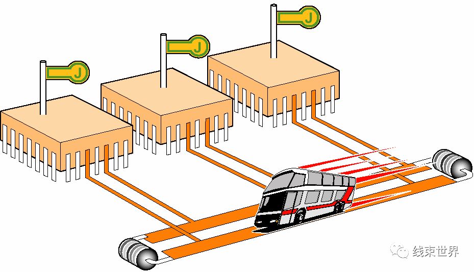
Figure2
As the number of electronic components in vehicles increases, there are dozens of ECUs, and all these electronic units need to exchange information. Traditional point-to-point communication can no longer meet the demand, so advanced bus technology must be adopted.The automotive bus is the communication network that connects in-vehicle devices or instruments at the lower layer of the in-vehicle network.Currently, there are four mainstream automotive buses: CAN bus, LIN bus, FlexRay bus, and MOST bus.
The applications of these four types of buses are generally as follows:
|
Bus Type |
Communication Speed |
Applications |
|
LIN |
10-125K (body) |
Headlights, lights, door locks, electric seats, etc. |
|
CAN |
125K-1M |
Automotive air conditioning, electronic indicators, fault detection, etc. |
|
FlexRay |
1M-10M |
Engine control, ABS, suspension control, steer-by-wire, etc. |
|
MOST |
Over 10M |
Automotive navigation systems, multimedia entertainment |
Or it can be described as follows:
CAN bus is the backbone, LIN is the assistant to CAN, FlexRay is the hope for the future, and MOST is responsible for cultural endeavors. These four buses will continue to shine in the future. Below, I will briefly introduce these four major buses.
FlexRay
FlexRay vehicle network standards have become the benchmark for similar products and will guide the development direction of automotive electronic product control structures for many years to come. FlexRay is the latest development after CAN and LIN, effectively managing multiple safety and comfort functions.
FlexRay is a registered trademark of DaimlerChrysler. The FlexRay Consortium has promoted the standardization of FlexRay, making it the next-generation in-vehicle network communication protocol. FlexRay focuses on some core demands of today’s automotive industry, including faster data rates, more flexible data communication, more comprehensive topology options, and fault tolerance.
Therefore, FlexRay can provide the necessary speed and reliability for the next generation of in-vehicle control systems. The maximum performance limit of CAN networks is 1Mbps. The maximum performance limit of LIN and K-LINE branch networks is 20Kbit/s. FlexRay can achieve a maximum data rate of 10Mbps on two channels, with a total data rate of up to 20Mbit/s, making FlexRay’s network bandwidth potentially 20 times that of CAN.
FlexRay can operate as a single-channel system like CAN and LIN networks, but it can also function as a dual-channel system. The dual-channel system can transmit data through a redundant network, which is an important feature of high-reliability systems.
Examples of FlexRay control applications include:
Steer-by-wire operations – typically using electronic control units
Anti-lock braking system (ABS) – includes vehicle stability control (VSC) and vehicle stability assistant (VSA)
FlexRay Node Operations
Each FlexRay node includes a controller and a driver component. The controller component includes a host processor and a communication controller. The driver component typically includes a bus driver and a bus monitor (optional). The bus driver connects the communication controller to the bus, and the bus monitor monitors the connection to the bus. The host notifies the bus monitor which time slots the communication controller has allocated. The bus monitor then only allows the communication controller to transmit data during those time slots and activates the bus driver. If the bus monitor detects a timing gap, it disconnects the communication channel.
The FlexRay nodes have several basic operating states:
Configuration state (default configuration/configuration) – for various initialization settings, including communication cycles and data rates
Ready state – for internal communication settings
Wake-up state – used to wake up nodes that are not communicating. In this state, the node sends a wake-up signal to another node, waking it up and activating the bus driver, communication controller, and bus monitor.
Startup state – for clock synchronization and preparing for communication.
Normal state (active/passive) – a state where communication can occur
Interrupt state – indicates a communication interruption
After years of improvement, the FlexRay network standard has matured. BMW has applied FlexRay in the X5 with five ECUs (electronic control damping, main suspension control system, etc.), and in the next generation of products, 16 ECUs will be applied.
CAN Bus
CAN is short for Controller Area Network (CAN), developed by the renowned German company BOSCH known for automotive electronic products, and eventually became an international standard (ISO 11898). It is one of the most widely used field buses internationally. In North America and Western Europe, the CAN bus protocol has become the standard bus for automotive computer control systems and embedded industrial control local area networks, with the J1939 protocol specifically designed for large trucks and heavy machinery vehicles based on CAN as the underlying protocol.
The high performance and reliability of CAN have been recognized and widely applied in industrial automation, marine, medical devices, industrial equipment, etc. Field buses are one of the hot topics in today’s automation technology development and are known as the local area networks of the automation field. Their emergence provides strong technical support for real-time, reliable data communication between nodes in distributed control systems.
Advantages of CAN Bus
CAN belongs to the category of field buses, and it is a serial communication network that effectively supports distributed control or real-time control. Compared to many RS-485-based distributed control systems, the distributed control system based on the CAN bus has obvious advantages in the following aspects:
Real-time data communication between network nodes
First, the CAN controller works in various modes, and each node in the network can compete to send data to the bus using a lossless structure of bit arbitration based on bus access priority (determined by message identifiers), and the CAN protocol eliminates station address coding in favor of coding the communication data, allowing different nodes to receive the same data simultaneously. These features make the data communication between nodes in a network constructed by CAN bus real-time and make it easy to create a redundant structure, improving system reliability and flexibility. In contrast, RS-485 can only form a master-slave structure, and the communication method can only be polling by the master station, resulting in poorer real-time performance and reliability.
Short Development Cycle
The CAN bus connects to the physical bus through the CAN transceiver interface chip 82C250’s two output ends, CANH and CANL, where the CANH end can only be high or floating, while the CANL end can only be low or floating. This ensures that the phenomenon seen in RS-485 networks, where multiple nodes simultaneously send data to the bus, causing a short circuit and damaging certain nodes, does not occur. Furthermore, CAN nodes have an automatic shutdown function in case of severe errors to prevent operations of other nodes on the bus from being affected, ensuring that issues with individual nodes do not cause the bus to enter a “deadlock” state. Additionally, the complete communication protocol of CAN can be implemented by CAN controller chips and their interface chips, significantly reducing system development difficulty and shortening the development cycle, which is something that RS-485, with only electrical protocols, cannot compare with.
Established International Standard Field Bus
Moreover, compared to other field buses, the CAN bus is a well-established international standard with high communication speed, ease of implementation, and cost-effectiveness. These are also important reasons for the strong market competitiveness of the CAN bus in various fields.
One of the Most Promising Field Buses
CAN, or Controller Area Network, falls under the category of industrial field buses. Compared to general communication buses, CAN bus data communication features outstanding reliability, real-time performance, and flexibility. Due to its excellent performance and unique design, CAN bus is receiving increasing attention. Its application in the automotive field is the most extensive, with many renowned automobile manufacturers adopting CAN bus to facilitate data communication between automotive internal control systems and various detection and execution mechanisms. Additionally, due to the inherent characteristics of CAN bus, its application scope has expanded beyond the automotive industry to include automatic control, aerospace, marine, process industry, mechanical industry, textile machinery, agricultural machinery, robotics, CNC machine tools, medical devices, and sensors. CAN has established itself as an international standard and is recognized as one of the most promising field buses. Typical application protocols include: SAE J1939/ISO11783, CANOpen, CANaerospace, DeviceNet, NMEA 2000, etc.
Characteristics of CAN Bus
It is a multi-master bus, and the communication medium can be twisted pair, coaxial cable, or optical fiber. The maximum communication speed can reach 1Mbps.
Simple Structure
It only connects with two wires externally and integrates error detection and management modules internally.
Transmission Distance and Speed
Characteristics of CAN bus: (1) Data communication does not differentiate between master and slave; any node can initiate data communication with any other (one or more) nodes, relying on the priority order of information from each node to determine communication order. High-priority node information communicates in 134μs; (2) When multiple nodes initiate communication simultaneously, lower-priority nodes yield to higher-priority nodes, preventing congestion on the communication line; (3) The communication distance can reach up to 10KM (with a speed of less than 5Kbps) and can achieve a speed of 1Mbps (communication distance less than 40M); (4) The CAN bus transmission medium can be twisted pair or coaxial cable. CAN bus is suitable for high data volume short-distance communication or long-distance low data volume with high real-time requirements, used in multi-master multi-slave or equal node fields.
Examples of CAN Bus Applications
In the field of industrial control, CAN bus mainly uses low-speed fault-tolerant CAN, i.e., ISO11898-3 standard, while in the automotive field, it commonly uses 500Kbps high-speed CAN.
Some imported models have multiple control networks for body, comfort, multimedia, etc., where body control uses CAN network, comfort uses LIN network, and multimedia uses MOST network, with CAN network as the main network controlling the engine, transmission, ABS, and other body safety modules, sharing engine speed, vehicle speed, oil temperature, etc. across the entire vehicle to achieve intelligent control, such as automatically locking doors at high speeds, opening doors automatically when airbags deploy, and other functions.
CAN systems are divided into high-speed and low-speed; high-speed CAN systems use hardwired power type with a speed of 500kbps controlling ECUs, ABS, etc.; low-speed CAN is comfort type with a speed of 125Kbps, mainly controlling instruments, anti-theft, etc.
Application of CAN Bus in Automobiles
Using CAN bus can reduce body wiring, further saving costs. Due to the adoption of bus technology, signal transmission between modules only requires two signal wires. Wiring is localized, and all other wires that run across the body are no longer needed, saving wiring costs. The CAN bus system is data-stable and reliable, with low inter-wire interference and strong anti-interference capability. CAN bus is tailor-made for vehicles, fully considering the harsh working environment on cars, such as the strong back EMF generated when the ignition coil ignites, the surge current generated when the eddy current buffer is cut off, and the high temperature around 100°C in the engine compartment.
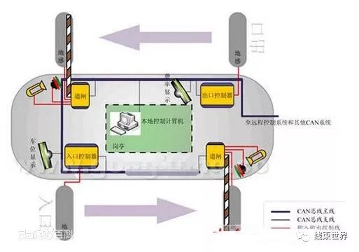
As safety features are increasingly emphasized, the number of airbags will gradually increase; previously, only one was installed in front of the driver, but now side and rear airbags will also be installed. These airbags sense collision signals through sensors and transmit the sensor signals to a central processor via the CAN bus to control the activation of each airbag. At the same time, advanced anti-theft designs are also based on CAN bus network technology. Firstly, the verification information confirming the legitimacy of the key is transmitted via the CAN network, improving encryption algorithms, making the verification information richer than previous anti-theft systems; secondly, the car key, anti-theft controller, and engine controller store each other’s information, and random codes are mixed into the verification code, making it impossible to decipher, thus enhancing the security of the anti-theft system. All these functions rely on the CAN bus, which has become the “anchor” of intelligent vehicle control.
In modern car design, CAN has become a necessary device. Brands like Mercedes-Benz, BMW, Volkswagen, Volvo, and Renault have adopted CAN as a means of connecting controllers. Reports indicate that China’s first hybrid car with a CAN network system has been successfully trial-installed by Chery and has undergone preliminary testing. The introduction of CAN bus technology has also begun in Shanghai Volkswagen’s Passat and POLO models. However, overall, the application of CAN bus technology in China’s automotive industry is still in the experimental and initial stages, with the vast majority of vehicles not yet adopting automotive bus designs. It is imperative for the domestic industry to enhance its study of network bus technology in terms of technology, design, and application.
LIN Bus
LIN bus is a low-cost serial communication network defined for distributed electronic systems in automobiles, serving as a complement to other automotive multiplex networks like Controller Area Network (CAN). It is suitable for applications that do not have high requirements for network bandwidth, performance, or fault tolerance. The LIN bus is based on the SCI (UART) data format, employing a single master controller/multiple slave device model, which is a special case of UART. The data transfer rate is 1-20Kb/s, and this rate is preset in the LIN control unit software, reaching a maximum of 1/5 of the comfortable CAN data transfer rate.
Overview of LIN Bus
LIN (Local Interconnect Network) is a low-cost serial communication network used to implement distributed electronic system control in automobiles. The goal of LIN is to provide auxiliary functions for existing automotive networks (such as CAN bus), making LIN bus a supplementary bus network. In situations where the bandwidth and multifunctionality of the CAN bus are not required, such as communication between intelligent sensors and braking devices, using LIN bus can greatly reduce costs.
The LIN technical specification defines not only the basic protocol and physical layer but also development tools and application software interfaces.
LIN communication is based on the SCI (UART) data format, employing a single master controller/multiple slave device model. It uses a single 12V bus and a node-synchronized clock line without a fixed time reference.
This low-cost serial communication mode and corresponding development environment have been standardized by the LIN Association. The standardization of LIN will reduce costs for automotive manufacturers and suppliers in developing application operating systems.
Characteristics of LIN Bus
Low cost: Based on the universal UART interface, almost all microcontrollers have the necessary hardware for LIN;
Very few signal lines can achieve the international standard ISO9141;
The transmission rate can reach a maximum of 20Kbit/s;
Single master controller/multiple slave device model does not require arbitration mechanisms;
Slave nodes can achieve self-synchronization without a crystal oscillator or ceramic resonator, saving hardware costs for slave devices;
Guarantees signal transmission delay time;
Nodes can be added to the network without changing the hardware and software of LIN slave nodes;
Typically, the number of nodes on a LIN network is less than 12, with a total of 64 identifiers;
Applications of LIN Bus
Typical LIN bus applications include automotive assembly units like doors, steering wheels, seats, air conditioning, lights, humidity sensors, and AC generators. For these cost-sensitive units, LIN enables the widespread use of mechanical components such as intelligent sensors, brakes, or photoelectric devices. These components can be easily connected to the automotive network and maintained and serviced conveniently. In systems implemented with LIN, analog signals are often replaced with digital signals, optimizing bus performance.
Using LIN in the following automotive electronic control systems will yield excellent results:
Car Roof
Humidity sensors, light-sensitive sensors, signal light control, car roof
Car Door
Window glass, central locking, window opening and closing, window lifters
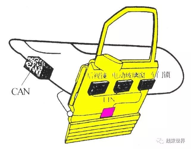
Car Door Bus Module Schematic
Car Head
Sensors, small motors
Steering Wheel
Steering control switches, wipers on the windshield, turn signals, radio, air conditioning, seats, seat control motors, speed sensors
Although LIN was initially designed for automotive electronic control systems, it can also be widely applied in industrial automation sensor buses and consumer electronics.
MOST Bus
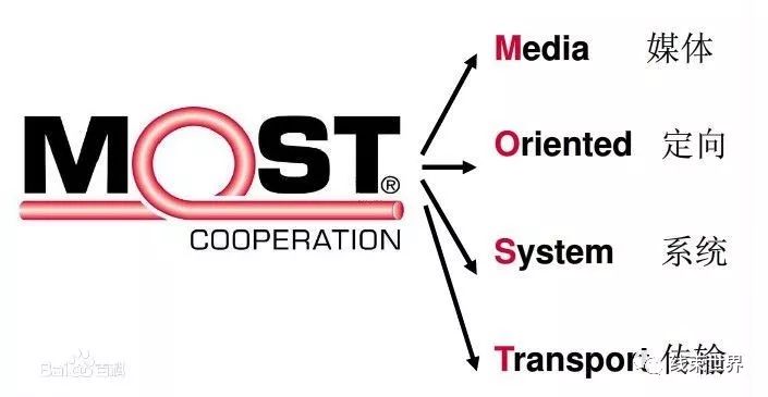
MOST (Media Oriented System Transport) is a media-oriented system transport bus, a result of collaboration in the automotive industry, lacking formal standards.
MOST Bus Product Introduction
MOST bus was a collaboration between BMW, DaimlerChrysler, Harman/Becker (audio system manufacturer), and Oasis Silicon Systems. Soon after (in 1998), the participating parties established an independent entity, the MOST Corporation, to control the definition work of the bus. Oasis retains the rights to the name MOST. An independent testing agency is responsible for the certification process of products, such as Ruetz Technology. In addition to compliance testing, Ruetz also provides software and hardware analysis tools for MOST bus system development and training.
The MOST bus is specifically designed to meet the stringent requirements of the automotive environment. This new fiber optic-based network can support data rates of 24.8Mbps, offering advantages over previous copper cables in terms of weight reduction and reduced electromagnetic interference (EMI).
MOST Bus Product Features
The MOST transmission protocol consists of data blocks segmented into frames, each frame containing streaming data, packet data, and control data.
At the physical layer, the transmission medium itself is protected with a plastic sheath, with a core of 1 mm PMMA (polymethyl methacrylate) optical fiber. OEM suppliers can bundle a bundle of optical fibers like electrical wires into an optical cable. Optical transmission uses a 650 nm (red) LED transmitter (650 nm is the low-loss “window” in the PMMA spectral response). Data is sent at 50 Mbaud, with a maximum data rate of 24.8 Mbps.
The definition of MOST is quite general, allowing for various topologies, including star and ring structures, with most automotive devices adopting a ring layout. A MOST network can have up to 64 nodes. Once the vehicle is powered on, all MOST nodes in the network are activated, which is a key focus for low-power and power-off mode design, including the amount of power consumed in that state and how to enter that state. The default state of MOST nodes when powered on is pass-through, meaning that incoming data is directly transmitted from the receiver to the transmitter to keep the loop open.
The data transfer for MOST uses 512 b frames and 16 frame blocks (Figure 1). Each frame contains not only preamble and other internal management bits but also synchronization, asynchronous, and control data. The bus is fully synchronized, allowing designers to designate any device in the network as the master device, while all other nodes obtain their clock from the master device. The network is completely plug-and-play, and when powered on or when connections change, there is a device discovery process. The master node maintains a central registry of connected devices.
Figure1: Typical In-Vehicle High-End Entertainment System Based on MOST Bus
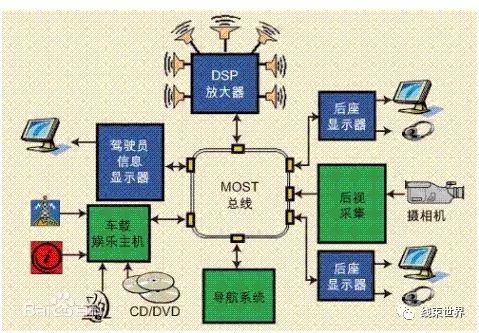
Figure2: Schematic Diagram of In-Vehicle Audio Entertainment System Based on MOST Bus

Previous Highlights
▸ Talk about the feelings of wiring engineers – swimming in a cesspool
▸ In-depth analysis of wire current carrying capacity
▸ Useful tools for Wire Harness!!!!!!!
▸ The origin of automotive wiring harnesses
Wiring World
WeChat Official Account: Wiring_World (Press and hold the QR code below to follow)
Scan the editor’s WeChat below for submissions or to join the technical group