This article highlights the structure of the GLA model’s onboard network system in a graphical format and introduces the network members. It also emphasizes the structure and location of the power management system components, provided for peer reference.
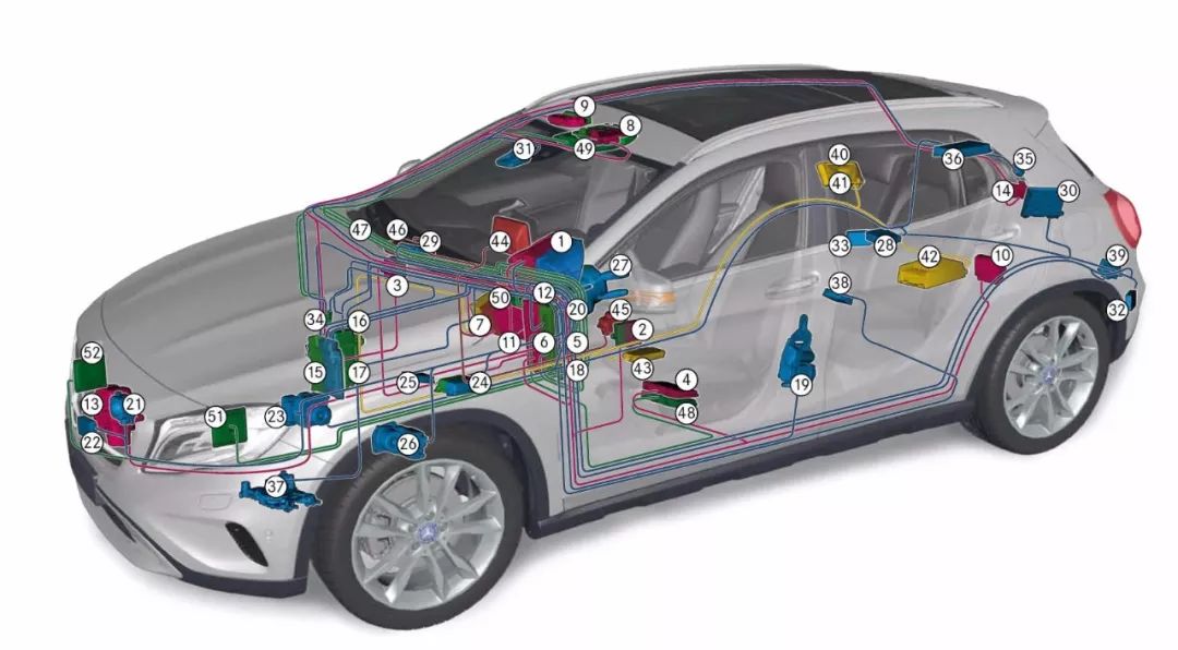
(Click the small image to view the high-definition large image)
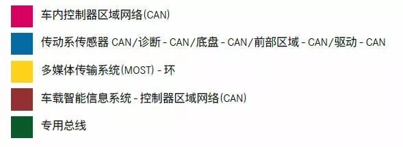
The illustration above explains (click the small image to view the high-definition large image)
In-Car Controller Area Network (CAN)
1 Instrument Cluster (KI)
2 Left Front Door Control Unit
3 Right Front Door Control Unit
4 Driver Seat Control Unit (with Memory Component)
5 Front Passenger Seat Control Unit
6 Central Body Controller (CBC) Control Unit
7 Cockpit Management and Data System (COMAND) (not shown: Audio 20)
8 Panoramic Sliding Sunroof
9 In-Car Control Unit, Anti-Trailer Protection
10 Trailer Recognition Control Unit
11 Automatic Climate Control Unit (KLA)
12 Electronic Ignition Switch (EZS)
Transmission Sensor – Controller Area Network (CAN)
17 Engine Electronic Device (ME) Engine Control Unit (Gasoline Engine)
18 Nitrogen Oxide Sensor Control Unit (M270)
21 Diesel Common Rail Direct Injection (CDI) Engine Control Unit (Diesel Engine)
56 Transmission Control Unit (for Engine 651.930)
13 Fixed Heater Control Unit
14 Trunk/Hatch Control Unit
Diagnostic Controller Area Network (CAN)
12 Electronic Ignition Switch (EZS)
29 Onboard Intelligent Information Service Communication Module
30 Emergency Call System Control Unit M I
Chassis Controller Area Network (CAN)
1 Instrument Cluster (KI)
12 Electronic Ignition Switch (EZS)
15 Engine Electronic Device (ME) Engine Control Unit (for M270)
17 Diesel Common Rail Direct Injection (CDI) Engine Control Unit (for OM651)
19 Left Front Reversible Seat Belt Emergency Tightener
20 Right Front Reversible Seat Belt Emergency Tightener
21 Distance Control System (DISTRONIC) Control Unit
22 Collision Prevention Assistance System Control Unit
23 Electronic Stability Program (ESP®) Control Unit
24 Auxiliary Protection Device Control Unit
25 Parking System Control Unit (Code 220), Parking Positioning System (PARKTRONIC) or
Active Parking Assistance System (Code 235)
26 Electronic Power Steering Control Unit (EPS)
27 Steering Column Tube Module (MRM)
28 Electric Parking Brake Control Unit
Front Area Controller Area Network (CAN)
12 Electronic Ignition Switch (EZS)
31 Multifunction Camera
32 Left Rear Radar Sensor
33 Right Rear Radar Sensor
34 Headlight Control Unit
35 Rearview Camera
36 Tire Pressure Monitoring System Control Unit
Transmission Sensor Controller Area Network
(CAN)
15 Engine Electronic Device (ME) Engine Control Unit (for M270)
16 Nitrogen Oxide Sensor Control Unit
17 Diesel Common Rail Direct Injection (CDI) Engine Control Unit (OM651.930)
18 Transmission Control Unit (OM651.930)
Multimedia Transmission System (MOST) – Ring
7 Cockpit Management and Data System (COMAND) (not shown: Audio20)
40 Digital Audio Broadcasting (DAB)
41 Satellite Digital Audio Broadcasting (SDAR)
42 Audio System Amplifier Control Unit
43 Multimedia Interface
In-Car Intelligent Information System Controller Area Network (CAN)
7 Cockpit Management and Data System (COMAND) (not shown: Audio20)
44 Audio/Cockpit Management and Data System (COMAND) Control Unit
45 Audio/Cockpit Management and Data System (COMAND) Display
46 Navigation Module
47 Navigation Module Bracket
Dedicated Bus
2 Left Front Door Control Unit
3 Right Front Door Control Unit
6 Central Body Controller (CBC) Control Unit
9 In-Car Control Unit, Anti-Trailer Protection
11 Automatic Climate Control (KLA)
12 Electronic Ignition Switch
15 Engine Electronic Device (ME) Engine Control Unit (M270)
17 Diesel Common Rail Direct Injection (CDI) Engine Control Unit (OM651)
24 Auxiliary Protection Device Control Unit
27 Steering Column Tube Module (MRM)
34 Headlight Control Unit
48 Driver Seat Control Unit (without Memory Component)
49 Roof Control Panel Control Unit
50 Upper Control Panel Control Unit
51 Left Front Actuator Control Module LED
52 Right Front Actuator Control Module LED
Battery/Generator
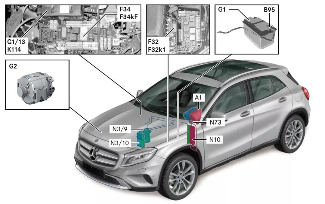
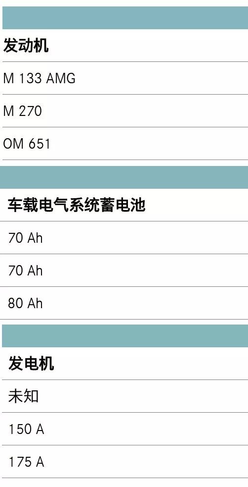
In all models, the onboard electrical system’s battery (G1) is located in the engine compartment, in the left rear direction of travel. In vehicles equipped with the ECO Start/Stop function, an additional battery (G1/13) is installed in the front passenger footwell.
By using a 12 Ah ECO Start/Stop function additional battery (G1/13), voltage disturbances (e.g., during radio or ventilation operation) are prevented from being felt by the occupants during engine start. At this time, the ECO Start/Stop function additional battery will supply power to the active electrical devices when the onboard electrical system battery is disconnected from the onboard electrical system (during engine start). Thus, the comfort functions in use will not be turned off.
Energy Management
Main Assembly Coordinator
The main assembly coordinator is integrated into the Diesel Common Rail Direct Injection System (CDI) control unit (diesel engine) or the Engine Electronic Device (ME) control unit (gasoline engine), forming the interface between the onboard electrical system management and the generator. The Diesel Common Rail Direct Injection System (CDI) or Engine Electronic Device (ME) control unit communicates with the generator via the Local Interconnect Network (LIN) (LIN C1). The main assembly coordinator regulates the generator’s power output according to the specifications of the onboard electrical system management, taking into account the engine load.
The following components detect and analyze the influencing factors related to this:
Central Body Controller (CBC) Control Unit;
Diesel Common Rail Direct Injection System (CDI) Control Unit or Engine Electronic Device (ME) Control Unit;
Generator.
Onboard Electrical System Management
The onboard electrical system management is used to monitor the utilization of the onboard electrical system and actively intervene in energy balance to ensure the starting capability of the engine andstabilize the power supply for all electrical devices. The following components play a decisive role in energy management:
Battery Sensor;
Onboard Electrical System Battery;
Generator;
Diesel Common Rail Direct Injection System (CDI) Control Unit or Engine Electronic Device (ME) Control Unit;
Central Body Controller (CBC) Control Unit;
ECO Start/Stop Function Additional Battery.
The Central Body Controller (CBC) Control Unit is used as the main control unit for energy management. Energy management includes the following sub-functions:
Driving Mode Energy Management;
Energy Management When the Engine is Off;
Engine Start/Stop Function Energy Management.
Generator Management
To reduce the load on the engine, the generator’s operating power is reduced when the battery charge is above 80%. The energy required in this operating state will be provided by the battery. If the driver then releases the throttle or stops the vehicle, kinetic energy recovery will occur during coasting and will be fed back into the battery (recovery).
[End of Article]