Click the blue text to follow us
1
Task Objective
This task focuses on the analog functionality of the Siemens S7-1200 PLC, with the core scenario being “analog control of Delta frequency inverter to achieve motor speed control”.
The analog module of the S7-1200 PLC can achieve dual functions:
First, it outputs analog signals to control actuators such as electric valves and inverters.
Second, it collects analog data from sensors such as temperature, pressure, liquid level, and flow. This task emphasizes the former to complete speed control.
2
Task Description
A certain equipment manufacturer needs to configure a cooling system for its equipment, using the control logic of “PLC analog control of Delta frequency inverter, inverter drives motor speed”. The system supports switching between manual and automatic modes (as shown in Figure 1), with specific functional requirements as follows:
1. Manual Mode
Allows direct operation to achieve basic controls such as forward, reverse, and stop of the motor, used for equipment debugging and status testing.2. Automatic ModeAutomatically adjusts the inverter output frequency to control motor speed based on the temperature signal collected from an external temperature sensor:1. When the temperature < 30℃, the inverter operates at a frequency of 20Hz2. When 30℃ ≤ temperature ≤ 40℃, the inverter operates at a frequency of 30Hz3. When the temperature > 40℃, the inverter operates at a frequency of 50Hz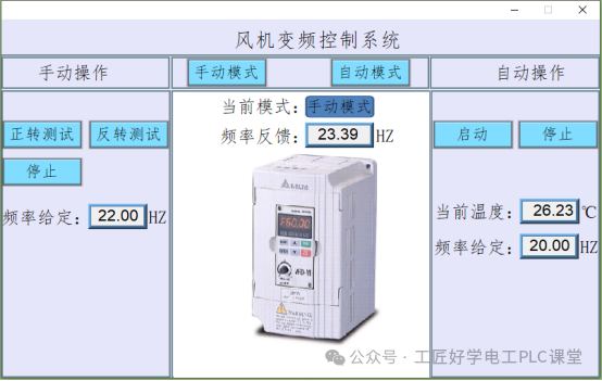
Figure 1: Fan Frequency Control Screen
3
Related Knowledge
The Delta VFD-M model frequency inverter is used in this case. When controlling the Delta frequency inverter with a PLC, relevant parameters need to be set.
This case requires the terminal to start the inverter and control the frequency of the inverter with analog signals. The wiring diagram between the PLC and the inverter is shown in Figure 2; the parameter settings for the inverter are shown in Figure 3.
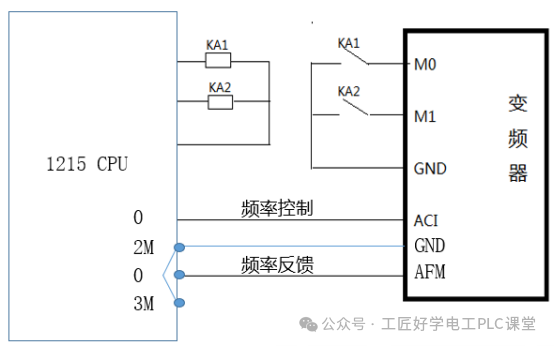
Figure 2: Wiring Diagram of PLC and Inverter
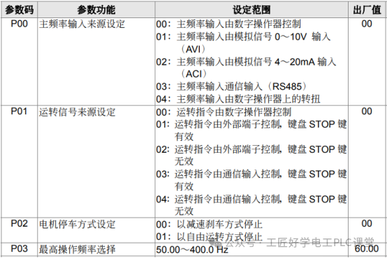
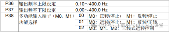


Figure 3: Parameter Settings of the Inverter
4
Inverter Parameter Settings
The following core parameters need to be configured to control the Delta inverter:
Frequency source selection: P00=02 (designated frequency setting method)
Command source selection: P01=01 (set control command input method)Stop mode: P02=00 (define motor stop mode)
5
Operating Frequency Limit
Operating frequency limit, maximum operable frequency P03=50.0Hz
Maximum output frequency P36=50.0Hz, minimum output frequency P37=0.0Hz
6
Terminal Function Definition
P38=00 (set the function mode of terminals M0 and M1)
Current – Frequency Correspondence
Minimum frequency (0Hz) corresponds to current value P131=0.0mA
Maximum frequency (50Hz) corresponds to current value P132=20.0mA
7
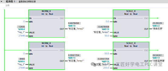
Normalization and Scaling Instructions (NORM_X)
Function Description:
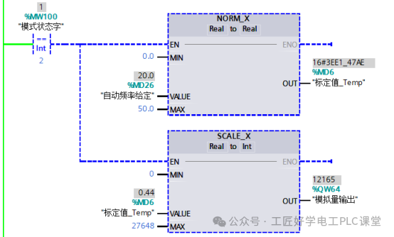
The normalization instruction (NORM_X) is used to linearly convert the input value (VALUE) within a specified range (MIN to MAX) to a normalized value (OUT) in the range of 0.0~1.0, with the calculation formula:
OUT = (VALUE – MIN) / (MAX – MIN)
(The result is automatically limited to the range of 0.0≤OUT≤1.0)
Application Example:
This instruction can convert physical quantities collected by sensors (such as temperature signals) or analog outputs from the PLC (such as current signals) into standardized values for subsequent logical processing (instruction example shown in Figure 4)
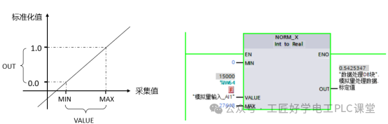
Figure 4: Normalization Instruction
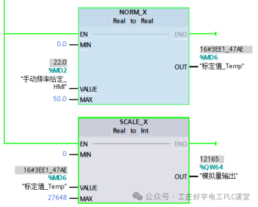
2. The scaling instruction (SCALE_X) is used to linearly convert the normalized real parameter (VALUE) in the range of 0.0~1.0 according to the specified data type and value range of parameters MIN and MAX, with the calculation formula:
<span>OUT = VALUE * (MAX - MIN) + MIN</span>(The input value VALUE must satisfy 0.0≤VALUE≤1.0), instruction example shown in Figure 5.
This instruction can convert the normalized ratio value (such as the output of NORM_X) into actual physical quantities or control quantities (such as the frequency setting value of the inverter, valve opening, etc.), achieving mapping from abstract ratios to specific values.
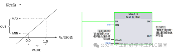
Figure 5: Scaling Instruction
4
Task Implementation
The implementation of this task mainly consists of three core steps: PLC wiring, I/O address allocation, and program design ideas.
1
PLC Wiring
Complete the hardware wiring as shown in Figure 6, ensuring accurate circuit connections between the S7-1200 PLC and external devices such as Delta inverters, temperature sensors, and mode switching switches.
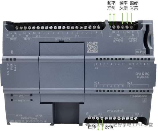
Figure 6: PLC Wiring Diagram
2
I/O Address Allocation
|
Input Address |
Description |
Output Address |
Description |
|
IW64 |
Frequency Feedback |
Q0.0 |
Forward |
|
IW66 |
Temperature |
Q0.1 |
Reverse |
|
QW64 |
Frequency Control |
3
Program Design Ideas
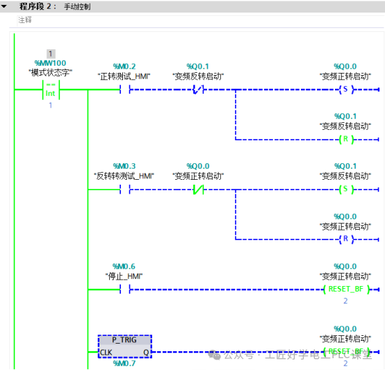
This task adopts the architecture of “PLC analog control + touch screen interaction” to implement inverter control: the PLC outputs analog signals to control the operation of the inverter, and the touch screen is responsible for frequency setting and status feedback display. The core of the system supports switching between manual and automatic dual modes, with specific control logic as follows:
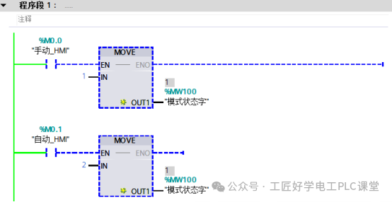
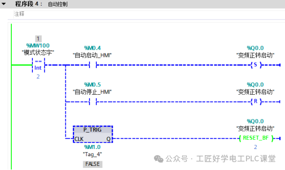
1. Mode Storage and Switching
Using register MW100 as the mode state storage medium: when MW100=1, the system switches to manual mode; when MW100=2, the system switches to automatic mode, achieving precise identification and switching of the dual modes through this register.
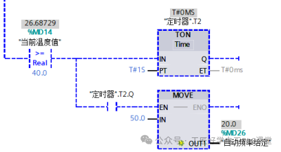
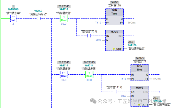
2. Dual Mode Frequency Control LogicManual Mode: Directly set the target frequency through the touch screen, and after the PLC receives the set value, it is transmitted to the inverter via the analog output module, achieving manual adjustment of the frequency.Automatic Mode: Based on real-time data collected from the temperature sensor, the frequency output value is determined by comparison instructions — when the temperature < 30℃, set to 20Hz; when 30℃ ≤ temperature ≤ 40℃, set to 30Hz; when temperature > 40℃, set to 50Hz, achieving automatic frequency adaptation.Fluctuation Prevention Optimization Design: Considering that the temperature measurement values from sensors can be easily affected by environmental factors, leading to fluctuations that may cause frequent frequency jumps, the system adds a timer delay mechanism: when the temperature triggers the frequency switching condition, the timer starts counting, and only if the switching condition is still met after the delay ends will the frequency set value be updated, avoiding control chaos caused by instantaneous fluctuations.
3
4. Program Design
 If this article is helpful to you, feel free to follow our public account and like and shareAdd the teacherto receive for free!Essential materials for Electrician PLC RobotsUseful for both beginners and advanced usersAdd the teacher’s WeChatto receive
 Your shares, likes, and views are all appreciatedI like them all