
Fire Prevention Before Ignition, Rely on Love for Safety
Click on “Yi Ai Fire Protection” above to subscribe
 Technical GuidanceYi Ai Fire Protection
36V Centralized Power Control Fire Emergency Lighting and Evacuation Indication System
 System Wiring and Cable Selection
The communication trunk (RS485 communication line) of the emergency lighting controller and the two-wire emergency lighting centralized power supply should be routed through weak current shafts (weak current bridges) according to GB50166 regulations. To ensure communication reliability, it is recommended to use NH-RVSP-2*1.5mm² shielded twisted pair; the two-wire centralized power supply connects directly to the two-wire emergency lighting fixtures via two buses, with the bus recommended to use WDZN-RYJS-2*2.5/4mm² cable or NH-RVS2*2.5 mm² twisted pair.
System Construction Precautions
To ensure the functionality and normal operation of the emergency lighting and evacuation indication system, construction should strictly follow the “system schematic diagram” and the above “wiring and cable selection”, GB50166-2019, GB51309-2018, and other requirements. The specific requirements for construction precautions are as follows:
1
The controller is installed in the fire control room, and the centralized power supply is installed in the fire control room, low-voltage distribution room, distribution room, or electrical vertical shaft. The main power supply of the controller and centralized power supply should be taken from the fire power supply AC220V/50HZ, the use of power plugs is strictly prohibited, and grounding must be secure.
2
The communication line should be kept away from interference sources, the communication line should run through weak current shafts or weak current bridges to ensure that communication transmission is not affected by strong current or radio frequency signal interference.
3
During system wiring, intermediate connections are prohibited; joints should be brought to the junction box. Joints should be connected by soldering and wrapped with electrical tape.
4
Ground embedded marker lights are for indoor use, use a dedicated embedded base, and construct according to GB51309 requirements. The lamps should be wired using soldering methods and secured with wire caps and sealed with waterproof sealant. Note: The construction steps for ground embedded lights refer to the “Design Manual”.
5
All lamps must have their addresses set using an encoder (1-128) before installation, or at least their serial numbers recorded in the corresponding locations on the floor plan.
6
The RS485 communication trunk between the centralized power supply and the controller should adopt a series connection method, i.e., “hand-in-hand” method; if it is inconvenient to adopt the hand-in-hand method for the entire project, it can be partially adopted, and then connected through a J-EI6412 network hub and controller.
7
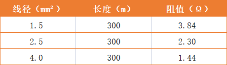
The two-wire bus of the 36V lamps can adopt any wiring method, but series wiring is recommended. If there are branches, one branch should be set (considering the difficulty of cable joint technology and loop crimping voltage drop). The voltage at the end of the bus line should be greater than 25V (the load capacity of the system is described in the configuration instructions). Refer to the table below to calculate the power that the line can carry.
Preparation Matters Before DebuggingPreliminary Preparation Work
1) A fire emergency lighting coding table should be provided. A complete coding table should generally include serial number, lamp function description, product number (serial number), loop/address number, address location description, etc. A detailed coding table helps with quick programming and troubleshooting.
2) CAD drawings of the system diagram and floor plan should be prepared, and in wmf format, with each drawing less than 1M. If the fire alarm controller is linked by protocol, a coding table for fire alarm controller components and a floor location map should be prepared.
Debugging Condition Check
1) Before the construction of the system wiring, technical communication should be carried out with our company to finalize the cable selection, laying methods, installation methods, and other matters.
2) Before system debugging, the installation of equipment and lamps should be completed, and the grounding of the controller and power supply should be checked to ensure reliable grounding.
3) Before debugging the system, each loop’s bus should be checked and measured according to GB51309, GB50166 requirements, confirming that the selected cable type and laying methods meet design requirements, and eliminate abnormal issues such as circuit short circuit, open circuit, and grounding, ensuring the insulation resistance of the line to ground.
4) After the main power of the controller and centralized power supply is stable, the debugging phase can begin. For the linkage debugging with the fire alarm system, the purchaser is responsible for coordinating with the fire alarm manufacturer: confirm the linkage method (dry contact linkage, protocol linkage), communication interface, and other information. If it is protocol linkage, the fire alarm manufacturer needs to provide the communication protocol and relevant interface boards, and our technical personnel will conduct linkage debugging work after receiving the protocol.
|Professional·Quality·Value|

China’s Leading Fire Alarm and Extinguishing Equipment Supplier