Mr. Big Cat says:
Translation of Chapter 11 from the compilation RFSoC-Book, details of this book can be found in the first article of this series.
“An open-source masterpiece, ‘Software Defined Radio Based on Zynq UltraScale+ RFSoC'”
Mr. Big Cat, WeChat public account: Mr. Big Cat’s Bookshelf, an open-source masterpiece, ‘Software Defined Radio Based on Zynq UltraScale+ RFSoC’
RF-DAC Working PrinciplesIn previous chapters, we have discussed various receiver architectures utilizing RF-ADC on RFSoC. Similarly, thanks to the RF-DAC’s ability to output real and complex signals, RFSoC also supports multiple transmitter architectures. The content regarding real and complex signal receiver architectures is detailed in Chapter 9, where many processing stages correspond closely to those in the transmitter architecture, just in reverse order. Therefore, this section will briefly describe the transmitter architecture and quickly transition to details more closely related to the characteristics of RF-DAC.Real Signal ArchitectureFor real signal output, there are mainly two options for the transmitter architecture: direct conversion to RF (Direct-RF) or introducing an intermediate frequency (IF) stage.In the Direct-RF architecture, the signal output from the RF-DAC is sent directly to the antenna via the analog front end (including filtering and amplification, etc.). If an IF stage is used, the output from the RF-DAC must undergo analog mixing to modulate the signal to a frequency higher than baseband but lower than the final RF carrier frequency. This method is typically chosen when the target RF frequency is too high, and the RF-DAC’s sampling rate is insufficient for direct generation.In either case, the output signal can be a pure real signal or an I/Q modulated signal. The key point is that the output of the RF-DAC is always a single-channel composite analog signal. Figure 11.22 illustrates these two architectures.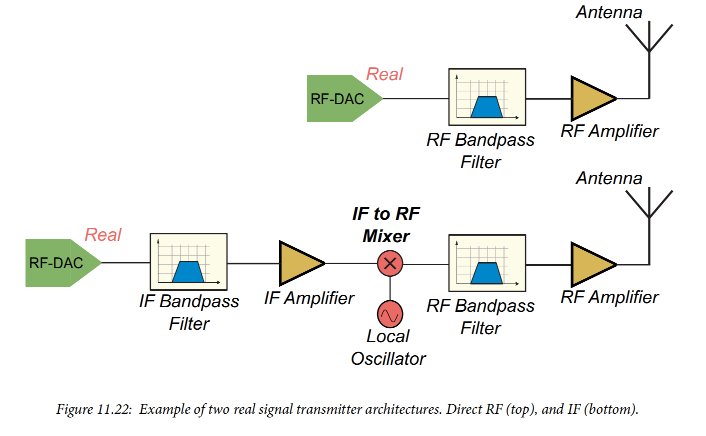 Complex Signal ArchitectureIn the complex signal architecture, the I and Q components are transmitted along independent signal paths internally and output as two analog signals from the RF-DAC with a phase difference of 90°. In this architecture, the synthesis of the I/Q signals occurs in the analog domain, and necessary phase or gain mismatch corrections are also performed at this stage.
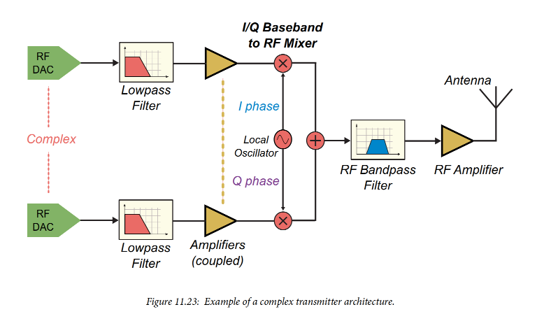 Figure 11.23 shows an example of a complex signal architecture. Since this transmitter directly implements modulation from baseband to RF, a low-pass filter is required to retain the baseband signal components and suppress spectral images from the second Nyquist zone and above. This differs from the real signal transmitter design shown in Figure 11.22, which modulates the signal to an intermediate frequency (IF) or RF in the digital domain, thus requiring a band-pass filter configured near the target signal bandwidth.Operating ModesTo support the above architectures, the RF-DAC can operate in two modes: Complex-to-Real (C2R) or Complex-to-Complex (C2C).In Complex-to-Real (C2R) mode, the I/Q output of the DUC (Digital Up Converter) is summed to form a single-channel signal, which is then sent to the analog output of the RF-DAC. In this mode: a Quad RF-DAC tile can output 4 independent channels on a single tile; a Dual RF-DAC tile can output 2 independent channels.In Complex-to-Complex (C2C) mode, the I/Q outputs of the DUC remain separated throughout the data path. At the cross switch (see Figures 11.11 and 11.13): the Q signal is routed to the odd-numbered RF-DAC; the I signal continues to the even-numbered RF-DAC. Ultimately, these two signals are sent to two independent RF-DAC analog outputs. In this mode: a Quad RF-DAC tile can output 2 independent C2C channels; a Dual RF-DAC tile can only output 1 C2C channel.Whether in C2R or C2C mode, a DUC is required. The data input to the RF-DAC tile must be an AXI4-Stream signal, where the I and Q channels are input in concatenated form. The Gearbox FIFO serves to separate the complex signal into I and Q components.Additionally, there is a real signal pass-through mode: the input signal is a real signal that is directly passed to the RF-DAC analog output. This mode has two configuration options:Pass-through Mode: The real signal is sent directly from the input to the analog output, completely bypassing the DUC, thus no mixing or interpolation can occur.Coarse Mixer Mode: If mixing and interpolation are required, a coarse mixer can be used, but its adjustable frequency range is significantly limited. If a fine mixer must be used, it can be achieved through C2R mode by setting the imaginary part (Q component) of the input concatenated signal to all zeros.Transmission of Multiple BandsA single RF-DAC can simultaneously transmit multiple signals modulated onto different carriers. This is achieved through multi-band mode: multiple signals are combined into a composite signal at the analog output. Multi-band mode is implemented by using multiple DUCs within a single tile: each DUC processes one signal; the outputs of each DUC are combined into a composite signal; since a DUC must be used, this mode cannot bypass the DUC. In multi-band mode, the delays between the DUCs within the tile are automatically kept in sync.Each tile can be configured for: real dual-band, I/Q dual-band; real quad-band, I/Q quad-band. The first two modes require two DUCs, while the latter two modes require four. All DUCs must be configured to the same mode. For example: if the I/Q quad-band mode is selected, all 4 DUCs must be set to I/Q output. In real signal mode, there is only one analog RF-DAC output; in I/Q mode, two RF-DAC analog outputs are required (odd-numbered RF-DAC for the real part, even-numbered for the imaginary part, consistent with C2C mode).Note:The Dual RF-DAC tile has only 2 analog outputs but contains 4 DUCs, thus it can support both dual-band and quad-band modes, while also supporting both real signal and I/Q outputs.The Single RF-DAC tile also contains 4 DUCs, thus it also supports multi-band mode. However, due to having only 1 analog output, it cannot achieve the transmission of I/Q separated channels.Since multiple signals are summed in multi-band mode, there is a risk of overflow. To avoid this issue, the system automatically applies attenuation at the outputs of each DUC: dual-band mode: 6 dB attenuation per channel; quad-band mode: 12 dB attenuation per channel. If necessary, attenuation can be disabled through software configuration.Example:A Quad RF-DAC tile can simultaneously transmit 4 different signals within the same Nyquist zone. Four independent inputs must be provided from the PL (Programmable Logic) to the RF-DAC tile. Each signal is up-converted to the specified carrier frequency through its respective DUC. Subsequently, the outputs of all DUCs are summed to form a composite signal, which is transmitted through the DAC0 data path. If needed, the composite signal can be further sent to the IMR (Image Suppression Filter) and anti-sinc filter, and finally converted to an analog signal output by the RF-DAC. Figure 11.24 illustrates this data path.
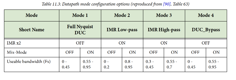
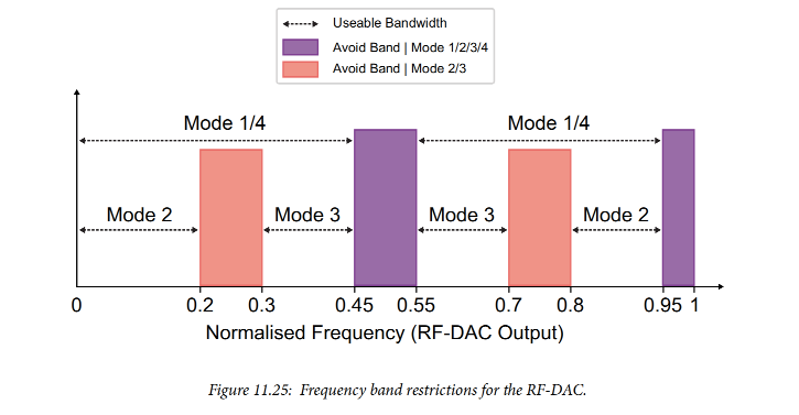
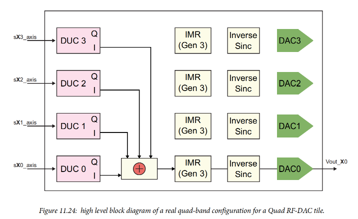 Application of Nyquist Zones in Real ScenariosIn the earlier part of this chapter, we have discussed the basic principles of Digital-to-Analog Conversion (DAC) and the role of filters in suppressing signal images. Typically, an analog reconstruction filter is used at the DAC output to eliminate these images: First Nyquist Zone (Nyquist Zone 1): using a low-pass filter; Second Nyquist Zone (Nyquist Zone 2): using a band-pass filter; both with bandwidth equal to the width of a single Nyquist zone.Ideally, such filters should have a “brick wall response,” capable of completely eliminating spectral components outside the passband. However, in practical applications, filters always have a transition band: that is, between the cutoff frequency and the stopband, the amplitude-frequency response gradually attenuates rather than exhibiting an ideal vertical drop. This has a certain impact on signal transmission: when the signal is at the edge of the Nyquist zone, its corresponding image may not be sufficiently suppressed by the reconstruction filter. Therefore, it is recommended to avoid transmitting intermediate frequency (IF) or radio frequency (RF) modulated signals in the edge region of the Nyquist zone (typically ±5% of the sampling rate).For designs using Gen3 devices with IMR (Image Suppression Filter), further considerations are needed: as shown in Figure 11.21, the low-pass and high-pass filters of the IMR have insufficient suppression capability near the edge of the Nyquist zone. Since the IMR introduces 2x interpolation after mixing, it further narrows the frequency range of the input signal that the DUC can modulate. In this case, special care should be taken to avoid areas close to the edge of the Nyquist zone. It is important to note that when enabling IMR, the definition of the Nyquist zone is based on the sampling rate at the IMR input, not the output.