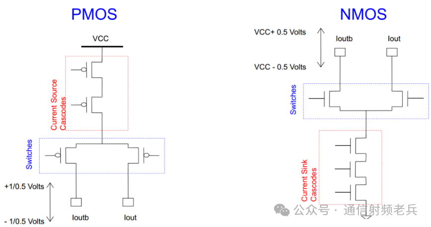
The DAC is not merely the reverse process of the ADC. The simplest architecture of a DAC is the current steering circuit. A DAC is designed to inject or extract a certain amount of current into or from a load. Ohm’s law relates this current to the output voltage. In this example, if the full-scale output of the DAC is 30 mA, and it is connected to a 50-ohm load, then the full-scale output voltage in this case will be 1.5 volts (single-ended) or 3.0 volts (peak-to-peak differential).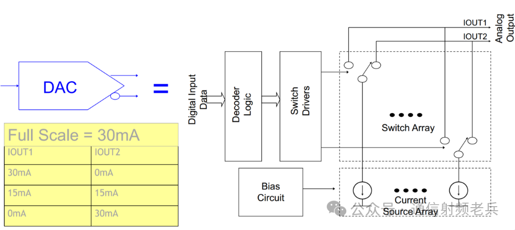 Current-steering digital-to-analog converters (DACs) can be either current sink or current source types. The difference lies in whether the current source for the DAC comes from the DAC power supply through the load resistor to ground, or from an external pull-up power supply through the load resistor, and then pulled to ground through the digital-to-analog converter.Current source DACs typically use P-channel devices as current sources, while current sink DACs usually employ N-channel transistors. In both cases, the output voltage is determined according to Ohm’s law by considering the amount of current flowing through the load resistor.
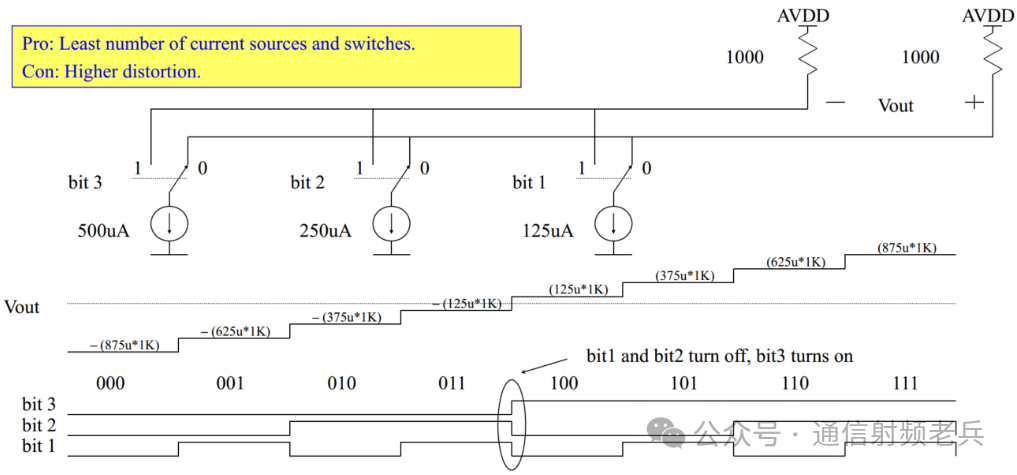
 Whether it is a current source or a current sink type, one way to implement the DAC output stage is to configure the output stage as a parallel combination of current mode drivers, where the current capability of each driver is scaled by a power of 2 relative to adjacent drivers. In this simple 3-bit example, the most significant bit (MSB) driver has a current capacity of 500 microamps, the next bit (middle bit) driver has a capacity of 250 microamps, and the least significant bit (LSB) driver has a capacity of 125 microamps. When all three drivers are activated, the full-scale output current is ±875 microamps.The advantage of this method is that for N-bit resolution, only N output drivers need to be designed to output in parallel. However, its disadvantage is that as the number of bits increases, it becomes difficult to match the output drivers because the tolerance of the MSB may be much greater than the expected resolution tolerance of the LSB. Unless the current capability of each bit is strictly scaled by powers of 2 from MSB to LSB and maintains the corresponding tolerances, the linearity of the DAC will be affected.
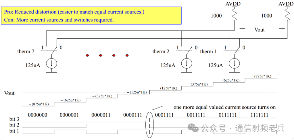
 Another method for DAC current output is to match the current capacity of the output drivers. In this approach, it is easier to maintain the tolerances of the output drivers, resulting in good matching from one driver to the next. However, for N-bit resolution, now 2^(N-1) output drivers are required. In the case of the 3-bit DAC shown, seven output drivers with the same current capacity would be needed. To achieve full-scale output, all drivers must be activated in parallel.In this example, the input sample code is converted from arithmetic code to thermometer code, and each thermometer code controls an individual output driver. This structure allows for better matching between output drivers, but for high-resolution sampling, the number of drivers required becomes quite large. A 14-bit digital-to-analog converter would require 16,535 output drivers in parallel.
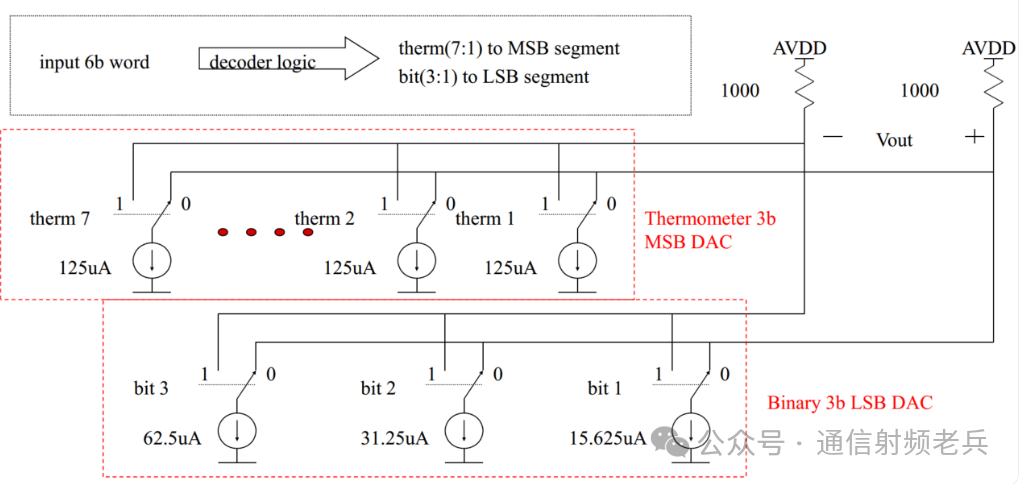
 To achieve higher resolution DACs, a combination of binary DACs and thermometer code DACs can be employed. In this example, a 6-bit DAC can use the high 3 bits of the sample value to control a thermometer code DAC, thus requiring only 7 matched current drivers in parallel. The low 3 bits can then be used to control another 3 current drivers, whose current values are scaled by powers of 2. This way, the matching range for current scaling only needs to cover up to 2^4. For DACs with higher resolutions like 14 to 16 bits, it is likely that this combination of encoding methods will be used.
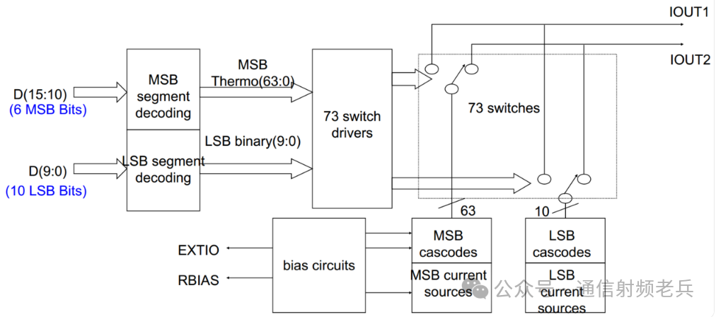
 For a 16-bit DAC, the high 6 bits of the sample value are converted into a 63-bit thermometer code to drive 63 matched current sources. Simultaneously, the low 10 bits of the sample value are directly used to drive another 10 scaled current sources, which are also connected in parallel with the 63 matched current sources. Therefore, the total number of current drivers is 73, and these 10 scaled binary current drivers must achieve good matching within the range of 2^11 (i.e., from 0 to 2047, but considering the actual levels of the current sources, it is within the range of 2048 levels from minimum to maximum current). That is, the current values of the 10 binary drivers are scaled within the range of 2^10 (i.e., from 1 to 1024, but the actual level numbers correspond to currents from 0 to 1023, emphasizing the scaling range), while the current values of the thermometer code drivers are all twice that of the maximum proportion driver current.