Mr. Big Cat says:
Translation compilation of Chapter 11 from the book RFSoC-Book, which is detailed in the first article of this series.
“An open-source masterpiece, ‘Software Defined Radio Based on Zynq UltraScale+ RFSoC'”
Mr. Big Cat, WeChat public account: Mr. Big Cat’s Little Bookshelf, an open-source masterpiece, ‘Software Defined Radio Based on Zynq UltraScale+ RFSoC’
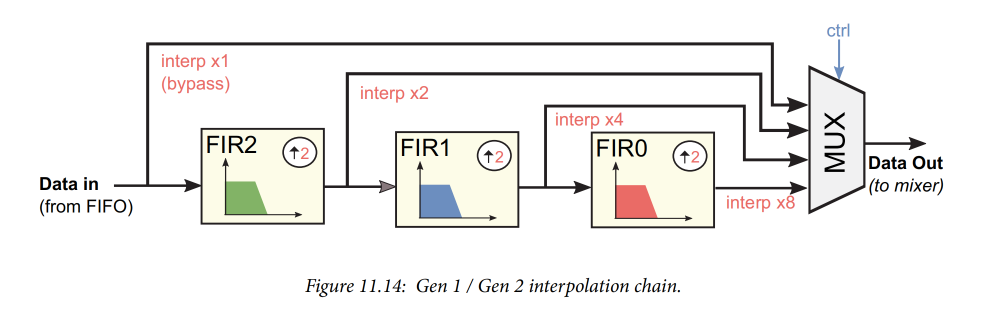
Programmable Interpolators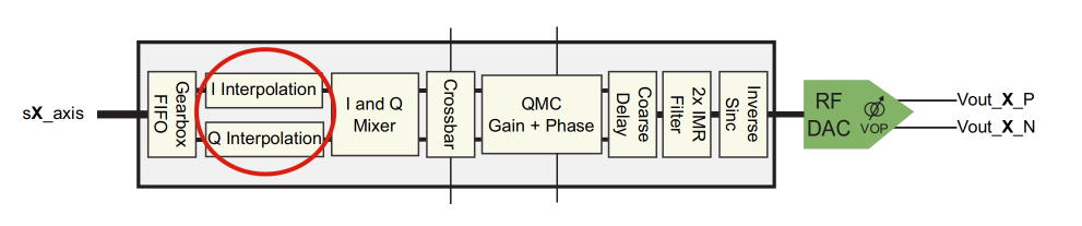 When data passes through the gearbox FIFO (as shown on the left side of Figure 11.13), the first processing stage increases the sampling rate, bringing it closer to (or equal to) the DAC sampling rate used for transmission. As mentioned earlier, interpolation is the process of increasing the signal sampling rate by inserting zeros (known as upsampling or zero-padding) between the original sample points, followed by filtering the resulting signal to remove the generated spectral images.In the RFSoC, the interpolation stage is part of the DUC and can operate in real mode or I/Q (complex) mode, depending on the configuration of the RF-DAC. The structure of the interpolation chain for the first and second generation devices differs from that of the third generation devices, as described below.First Generation / Second Generation Interpolation ChainIn the first and second generation devices, interpolation is achieved through three cascaded upsamplers and low-pass FIR filters, each performing a 2x rate change, referred to as FIR2, FIR1, and FIR0. Each filter stage can be bypassed, and the output of each stage can be routed to the final output of the interpolation chain, as shown in Figure 11.14.
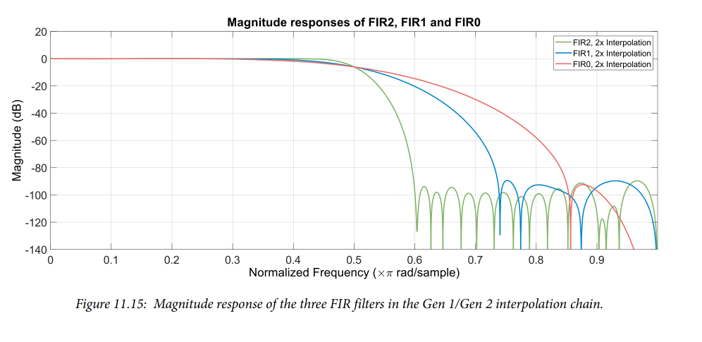
 Although the interpolation factor is user-programmable, the coefficients used for each FIR filter stage are fixed. The frequency responses of the three FIR filter stages are shown in Figure 11.15. Similar to the decimation chain of the RF-ADC, the first FIR filter stage has the steepest cutoff characteristics, while the responses of the subsequent filters gradually widen, as the gap between the signal and the spectral images that need to be attenuated increases. Each of the three interpolation stages can be selectively bypassed or cascaded, resulting in four different interpolation options: 1x (bypass), 2x, 4x, and 8x.
 Third Generation Interpolation ChainCompared to the first and second generation devices, the interpolator in the third generation devices has significantly improved rate change options. The interpolation chain consists of four cascaded stages, and like previous generations, each stage can be selectively bypassed. Figure 11.16 shows the block diagram of the third generation interpolation chain.
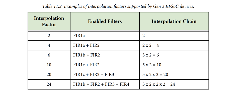
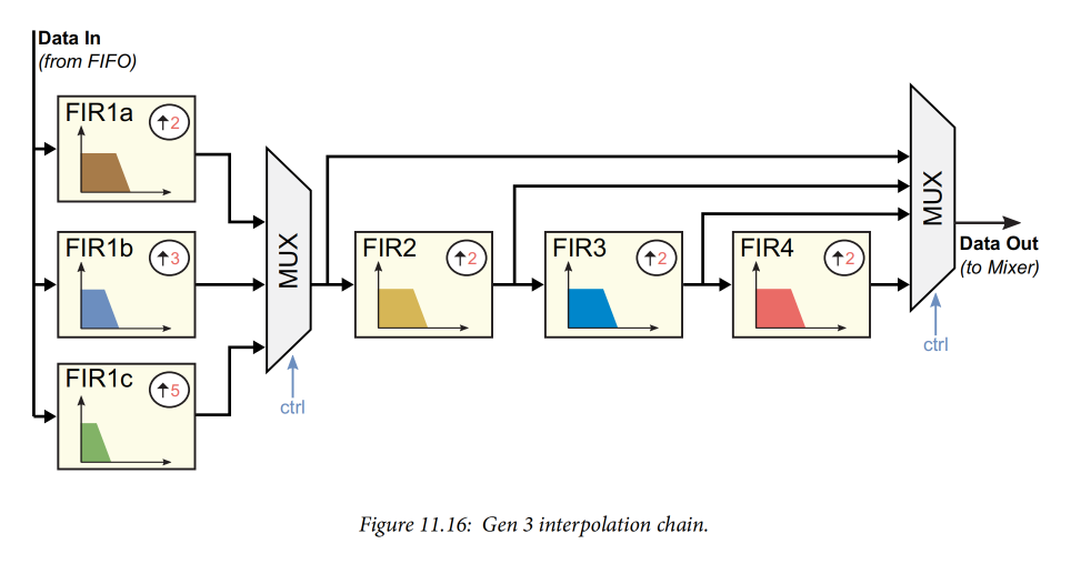 By combining these filter stages, the third generation interpolation chain can achieve the interpolation rates listed earlier: 1, 2, 3, 4, 5, 6, 8, 10, 12, 16, 20, 24, and 40. Table 11.2 provides some examples of how these filter stages can be cascaded to produce each possible interpolation factor.
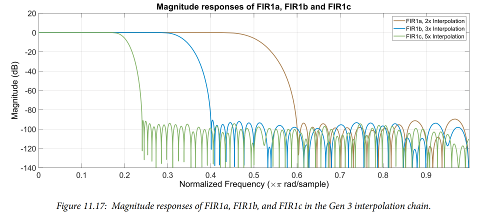
 The first stage of the interpolation chain consists of three multiplexed upsamplers and low-pass FIR filters, referred to as FIR1a, FIR1b, and FIR1c; they support 2x, 3x, or 5x interpolation, respectively. Only one of these filters can be used at any given time. Since these filters are collectively referred to as the first stage of the chain, they have a steeper transition band compared to subsequent stages. The frequency responses of the individual filters in the first stage are shown in Figure 11.17.
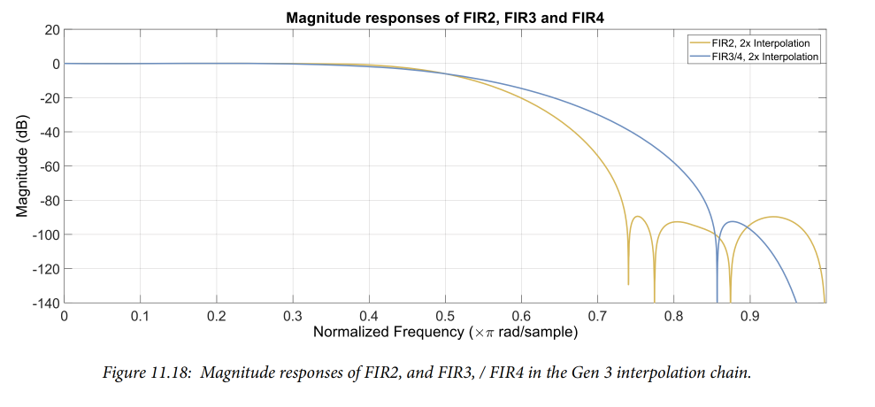
 The second, third, and fourth stages of the interpolation chain all have a 2x interpolation factor, and each stage can be individually bypassed. Similar to the interpolation chain in previous generation devices, the response of each subsequent filter is more relaxed, with FIR3 and FIR4 having the same response. The frequency responses of stages 2, 3, and 4 are shown in Figure 11.18;