1. CANopen Motor Drive and Motion Control Sub-protocol DS-402
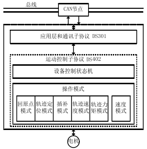
CANopen has developed relevant device sub-protocols DS-402 for motor drive and motion control devices, which standardizes the operation modes and parameters of servo drives, motion control cards, inverters, and other devices, greatly reducing development workload and improving device interconnectivity. From Figure 2-17, the CANopen control interface communication structure shows that the DS-402 device sub-protocol mainly defines the device control state machine and six operation modes: Homing Mode, Profile Position Mode, Interpolated Position Mode, Profile Velocity Mode, Profile Torque Mode, and Velocity Mode.
As mentioned earlier, the parameters of the DS-402 device sub-protocol are defined in 6000H-9FFFH.
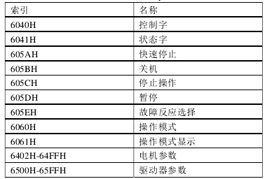
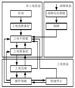
By modifying the control word and status word, the drive’s operation mode and running state can be changed. The range 605AH-605EH provides quick commands for operating the drive, while 6060H and 6061H serve as dual buffers for operation mode and operation mode selection. When the user modifies the control word, the operation mode and display still show the previous task’s operation mode if the previous task has not been completed. The servo system is a combination of high and low voltage devices, and because the controlled object is a motion mechanism, the safety and reliability requirements of the system are higher. Therefore, DS-402 defines a more complex and complete state machine.
2 Digital AC Servo Drive Hardware and Software Design
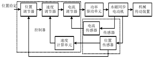
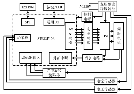
The structure of the digital AC servo system: The structure of the digital AC servo system is the same as that of traditional servo systems, consisting of a control computing unit, power drive unit, detection module, and permanent magnet synchronous motor, using a position, speed, and current three-loop control structure. As shown in the figure, the control unit is the core of the servo system, evolving from initial analog circuits, discrete components, and small-scale digital circuits to the current stage of large-scale integrated circuits. The position regulator, speed regulator, current regulator, speed calculation unit, as well as communication and fault detection advanced functions are implemented on a chip like DSP, MCU, or FPGA. Besides position sensors, there are also current and voltage sensors, and the accuracy of the sensors determines the upper limit of the entire servo system’s accuracy, making them very important.
The digital AC servo drive mainly consists of a control board, drive board, and sensors, as shown in Figure 3-2. The control unit is based on STMicroelectronics’ STM32F103 microprocessor with ARM Cortex-M3 core and its peripheral circuits, implementing vector control for permanent magnet synchronous motors, position regulators, speed regulators, current regulators, and PWM pulse generation algorithms. The chip also integrates interfaces for SPI, general IO, AD sampling, encoder input, and external interrupts, facilitating connections with peripheral circuits. The power drive unit includes a power module, IPM smart power module, and its protection circuit. The power module converts the 220V AC mains power through transformation, rectification, voltage stabilization, and filtering into various levels of DC voltage, providing power to the controller, IPM module, and various sensors.
3. Servo Drive Software Design
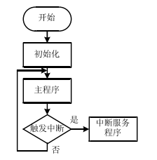
The servo drive adopts a modular programming approach, and the control system software can be divided into three parts: system initialization, main program, and vector control algorithm implementation unit. Upon powering the system, it immediately enters the initialization module to configure the system parameters, and then enters the main program loop. The vector control algorithm implementation unit is placed in the interrupt program, as shown in the overall design of the system software.
Initialization Program
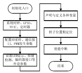
The system initialization mainly includes setting various parameter registers of the system and defining and initializing the running variables of various functional sub-modules. Specifically, this includes enabling and configuring processor modules such as system clock, general I/O ports, nested interrupt vector tables, timers, AD sampling, and communication interfaces, followed by declaring and initializing variables for each functional sub-module, enabling interrupts, completing initialization, and entering the main program. The system initialization flowchart is shown in the figure.
Main Program
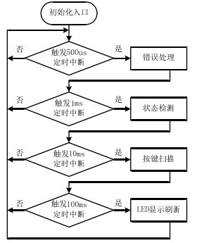
After the control system completes initialization, it enters the main program, which mainly handles running error processing, system status detection, LED display refresh, key scanning, data communication, and other functions. If all these task modules are placed in the loop sequentially, it will consume a large amount of system resources. Tasks such as LED display refresh and key scanning that do not require high real-time performance do not need to be executed at a high frequency. Therefore, the main program loop is divided into several time slices of different cycles, such as 500us, 1ms, 10ms, and 100ms. Based on the priority of the task sub-programs, they are placed in different time slices. The error handling module has the highest priority, running once every 500us, while system status detection is processed every 1ms. Lower priority tasks like key scanning and LED display refresh are placed in time slices of 10ms and 100ms, respectively. The structure of the control system main program is shown in the figure.
Interrupt Service Subroutine
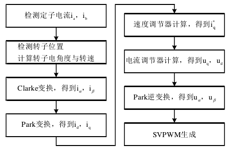
Modules that require high real-time performance, such as the implementation of vector control algorithms and short circuit protection, are completed in the interrupt service subroutine. The vector control algorithm is the core of the control system and first requires sampling and processing signals from sensors such as position, voltage, and current, calculating the motor rotor position and speed, completing the control algorithm, and generating PWM signals to drive the IPM module. The flowchart for implementing the vector control algorithm software is shown in the figure.
4. Implementation of CANopen Protocol Stack Object Dictionary
As mentioned before, the object dictionary is the data center of the CANopen substation, and its implementation difficulties lie in defining the object dictionary structure, searching, reading and writing the object dictionary, and setting the parameters of the object dictionary. The following will explain how this paper addresses these three problems.
4.1 Definition of Object Dictionary Data Types
Regarding the object dictionary, the controversy over using linked lists versus linear tables has been discussed previously, so it will not be repeated here. This paper defines all information of the object dictionary using structures and declares a structure array to store the object dictionary. Since the parameters required by the servo drive are basically fixed, we can trim the object dictionary items specified by the CANopen protocol and its sub-protocol DS-402, leaving only those entries required by the servo drive. At the same time, the STM32 standard peripheral library defines rich data types, allowing 8-bit and 16-bit unsigned integers to be directly defined as variables. Each entry format of the object dictionary is fixed. Thus, this method of storing object dictionary data not only avoids wasting storage space but also eliminates the use of pointers, saving system resources and facilitating the search and read/write of the object dictionary. The structure definition of the object dictionary entry is as follows:
typedef struct{
u16 index;
u8 subindex;
u8 length;
u8 access;
u8 data[4];
}OD_entry;
This structure defines the index, subindex, data length, read/write permissions, and data field of the object dictionary. During system initialization, an array of the required size OD[] is declared and initialized. When accessing the object dictionary, it is only necessary to traverse the structure array. Since the scale of servo system parameters is not particularly large, the search time is also acceptable.
4.2 Searching and Reading/Writing the Object Dictionary
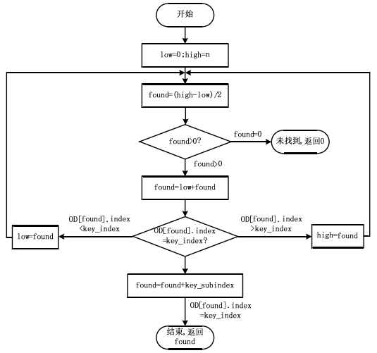
In the previous section, a static structure array was selected as the storage structure for the object dictionary, and all parameters are stored in the array in ascending order according to index and subindex. This structure does not support the insertion and deletion of object dictionary items; it only requires accessing specified entries by index and subindex for read and write operations. Therefore, the most important task is to find the position of the entry to be accessed in the structure array. Based on relevant knowledge of data structures, static search techniques generally include sequential search, binary search, and interpolation search. Sequential search is suitable for small-scale unordered static tables. If the length of the table is n, the average search length is (n+1)/2. Binary search is suitable for ordered sequences with an average search length of logn-1, while interpolation search has a shorter average search length but requires the static table to be both ordered and uniform. Therefore, we adopted binary search as the method for searching the object dictionary, using the function OD_Search(index, subindex) to return the index of the specified entry in the array. The program flowchart is shown in the figure.
4.3 Integration of Object Dictionary with Control Program
The previous section discussed the storage method of the object dictionary and how external devices access and read/write the object dictionary. This section will specifically discuss how the object dictionary integrates with the control program, focusing on the integration of existing parameters and newly added DS-402 protocol parameters, as well as the data exchange mechanism between the object dictionary and control program. The existing drive has already defined relevant parameters and state variables, which have separate storage space, and can be set and viewed through keys and LED displays. If these parameters are also stored in the object dictionary, it will lead to parameter inconsistency. As mentioned earlier, the index for the device manufacturer parameter definition area in the object dictionary is 2000H to 5FFFH, with a maximum of 256 subindexes, while the original drive parameters are 99 in number. Therefore, we only allocate the object dictionary index number 2000H for the original drive parameters, but do not allocate storage space; the parameters are still stored in the original parameter table, with the original parameter number serving as the subindex in the object dictionary. Upon receiving access and read/write requests for the object dictionary, the original drive parameters and the new parameters specified by DS-402 are searched separately, as shown in the search flowchart.

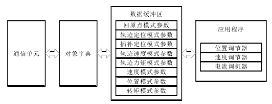
The data exchange mechanism between the object dictionary and control program is also worth considering. Drawing on the data exchange mechanism of original drive parameters and state variables, we define structure variables as data buffers for different operating states. The upper computer parameter settings and control commands immediately change the corresponding entries in the object dictionary, but the data buffer is only updated after the previous command is completed. Each module remains relatively independent, ensuring the safety of the control system. The principle of the data exchange mechanism is shown in the figure.
This article is reprinted from: “Research on AC Servo Drive Based on CANopen Protocol”
Author: Huang JianCollege of Electronic Information and Electrical Engineering, Hainan University