Introduction to CANopen Protocol: Multi-Device Collaborative Communication Design
In the field of industrial automation, multi-device collaborative communication is a common requirement. For example, multiple PLCs, sensors, and actuators on a production line need to coordinate with each other. To address this, the CANopen protocol was developed. It is a high-level protocol based on the CAN bus that helps us achieve efficient communication between multiple devices. Today, we will explain the basic concepts of the CANopen protocol, hardware connections, code implementation, and considerations in practical applications from scratch. Even if you are a beginner, you can grasp the core points through this article!
What is CANopen Protocol?
Basic Concept Explanation
CANopen = CAN + Application Layer Protocol.
-
CAN (Controller Area Network): A reliable communication bus commonly used in automotive and industrial control. Its characteristics include strong anti-interference, good real-time performance, and support for communication among multiple nodes.
-
CANopen: An application layer protocol added on top of the CAN bus that defines data formats, device addresses, communication methods, etc., allowing multiple devices to “understand” each other’s “language”.
Analogy: If we compare the CAN bus to a road, then CANopen is the traffic rules. There are vehicles on the road as hardware, and the vehicles must adhere to the traffic rules (CANopen protocol) to avoid “communication collisions”.
When to Use CANopen?
-
Multi-device collaboration on production lines, such as sensors collecting data and PLC controlling robotic arms.
-
Data exchange among various devices (different brands or models) in automation projects, such as factory equipment networking.
Hardware Circuit and Wiring
Components of CANopen Devices
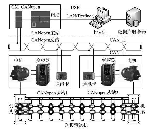
Each CANopen network typically includes the following components:
-
Master Node: Similar to a “commander”, such as a PLC or upper computer.
-
Slave Node: Executes specific tasks, such as sensors, actuators, etc.
-
Termination Resistors: Each end of the CAN bus needs to connect a 120-ohm termination resistor to prevent signal reflection.
Basic Wiring Diagram
1 Master Node (Power + MCU) --- CANH --- Slave Node 1 --- Slave Node 2 --- 120Ω
2                     CANL
Wiring Precautions:
-
CANH and CANL must correspond one-to-one; reversing them will lead to communication failure.
-
Termination Resistors: A 120Ω resistor must be connected at both ends of the bus. Forgetting to connect the resistor is a common mistake for beginners!
-
Bus Length: The theoretical maximum is 40 meters; if exceeded, the baud rate needs to be reduced.
Core Elements of CANopen Protocol
1. Node ID
Each device requires a unique ID (1-127). The master node is typically 1, while slave nodes are 2, 3, etc.
Note: ID conflicts can cause communication chaos, so be sure to check each device’s ID during debugging.
2. Object Dictionary (OD)
The object dictionary is the “data table” of CANopen devices, storing device parameters and status information, identified by hexadecimal addresses. For example, 0x1001 indicates the device error status.
| Number | Name | Description |
|---|---|---|
0x1000 |
Device Type | Identifies the category of the device (e.g., sensor) |
0x1001 |
Error Register | Records the device error status |
0x1018 |
Node ID | Sets the unique address of the device |
3. PDO and SDO
PDO (Process Data Object): Used for real-time data transmission, such as sensors transmitting temperature data. SDO (Service Data Object): Used for configuring and querying parameters, such as setting the node ID.
Simple Code Implementation: STM32 Control of CANopen Slave Node
We will implement a slave node program using the STM32 HAL library to read temperature sensor data and send it via PDO.
Hardware Requirements
-
STM32 development board (e.g., STM32F103C8T6)
-
MCP2551 CAN transceiver
-
Temperature sensor (e.g., DS18B20)
Code Example
The following code initializes the CAN bus of the STM32 and sends PDO data:
#include "stm32f1xx_hal.h" // HAL library header file

CAN_HandleTypeDef hcan; // Define CAN handle

// CAN initialization
void CAN_Config(void) {
    hcan.Instance = CAN1;
    hcan.Init.Prescaler = 16; // Baud rate 500kbps
    hcan.Init.Mode = CAN_MODE_NORMAL; // Normal mode
    hcan.Init.SyncJumpWidth = CAN_SJW_1TQ;
    hcan.Init.TimeSeg1 = CAN_BS1_4TQ;
    hcan.Init.TimeSeg2 = CAN_BS2_3TQ;
    hcan.Init.TimeTriggeredMode = DISABLE;
    hcan.Init.AutoBusOff = ENABLE;
    HAL_CAN_Init(&hcan);
}

// Send PDO
void Send_PDO(uint16_t device_id, uint8_t data) {
    CAN_TxHeaderTypeDef tx_header;
    uint8_t tx_data[8] = {data}; // Data
    uint32_t tx_mailbox;

    tx_header.StdId = 0x180 + device_id; // PDO ID
    tx_header.RTR = CAN_RTR_DATA;
    tx_header.IDE = CAN_ID_STD;
    tx_header.DLC = 1; // Data length 1 byte

    HAL_CAN_AddTxMessage(&hcan, &tx_header, tx_data, &tx_mailbox);
}

// Main function
int main(void) {
    HAL_Init();
    CAN_Config();

    while (1) {
        uint8_t temperature = Read_Temperature(); // Assume reading temperature
        Send_PDO(2, temperature); // Send temperature value to master node
        HAL_Delay(1000);
    }
}
Note: In the program, 0x180 + device_id is the standard ID of the PDO. The master node needs to listen to this ID to receive data.
Practical Application Case: Multi-Node Temperature Monitoring System
Requirement Description
There are multiple temperature sensors in the workshop, each acting as a CANopen slave node, transmitting temperature data to the PLC (master node) in real time. The PLC monitors the temperature and controls the fan.
Implementation Steps
-
Each sensor node is assigned a unique ID (e.g., 1, 2, 3).
-
The master node (PLC) receives the real-time temperature from each sensor via PDO.
-
If the temperature exceeds the set threshold, the PLC controls the fan to turn on via a relay.
Common Problems and Solutions
-
Device Communication Failure (No Response on Bus)
-
Check if the termination resistors are correctly installed.
-
Ensure the baud rate is consistent (master and slave nodes must match).
-
Use an oscilloscope to check the CANH and CANL signals.
Data Loss or Conflict
-
Ensure each node ID is unique.
-
Avoid too many nodes sending data at the same time; optimize the PDO sending period.
Debugging Difficulties
-
Use a CAN analyzer tool to view communication data on the bus and quickly locate issues.
Practical Recommendations
-
Recommended Tool: A CAN analyzer (e.g., USB-CAN module) is a powerful tool for debugging CANopen networks, allowing real-time viewing and analysis of bus data.
-
Testing Environment: Start with a simple structure of 1 master and 1 slave, gradually adding slave nodes to avoid difficulties in debugging when adding multiple devices at once.
-
Standardized Naming: Properly label the object dictionary parameters for each device to avoid difficulties in future maintenance.
Through this article, you have grasped the basic principles of the CANopen protocol, hardware connections, code implementation, and practical application cases. Go and practice, starting with simple applications and gradually delving deeper!