▲ Click☆to star me to avoid losing contact
1. Introduction
This time we will configure PWM output based on RTD, without further ado, let’s get started.
2. Configuration Steps
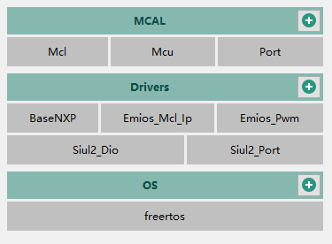
1. Load the driver
For this experiment, we need to add these configurations yourself.
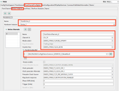
2. Port Configuration
Make the following configurations.
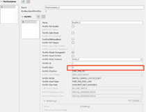
After entering 2 here, the following will be automatically recognized, select PTA2 as the EMIOS output pin, channel is EMIOS1_CH19_Y.
3. Mcl Configuration
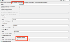
Configure in the order shown in the image to enable EMIOS.
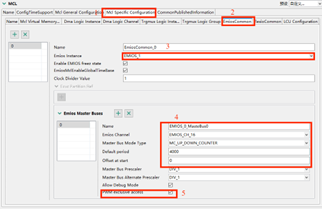
(1) Select EIOS_1
(2) Select EMIOS_CH_16 to configure the clock division for PWM output providing counter, at this point PWM frequency = 160M/1/4000/1/1 = 40K
(3) Enable debug mode and allow PWM exclusive access.
4. PWM Configuration
Configure the above settings as shown in the red box. At the same time
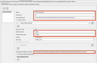
(1) Default division, configuration must be consistent with the MCL module configuration
(2) Duty cycle
(3) Clock source select system clock
3. API Interface
void Pwm_Init(const Pwm_ConfigType * ConfigPtr)//PWM initialization
void Mcl_Emios_SetCounterBusPeriod(uint16 logicChannel, uint32 period, boolean syncUpdate)//Set PWM frequency
void Pwm_SetDutyCycle(Pwm_ChannelType ChannelNumber, uint16 DutyCycle)//Set PWM duty cycle
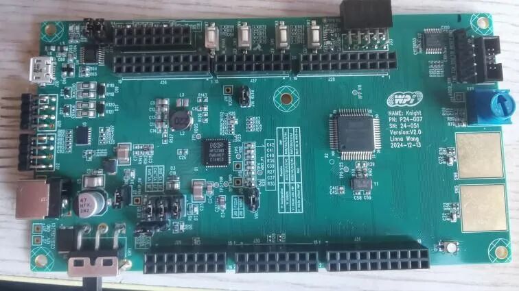
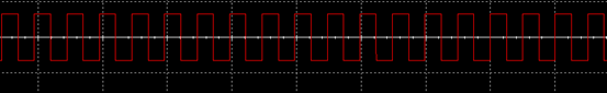
4. Results
This article is from the “S32K312 Development Board Review Activity” Reviewer: Fu Chuchu
For more related content on the S32K312 development board review, please follow the blogger Dada Tong: Automotive Expert.
Welcome to follow the blogger Dada Tong:Automotive Expert
Learn more about automotive application knowledge!

Welcome to follow the Dalian Engineer Community – Dada Tong
👇👇👇

ClickRead the original text to learn more details!

Like
Collect
Share