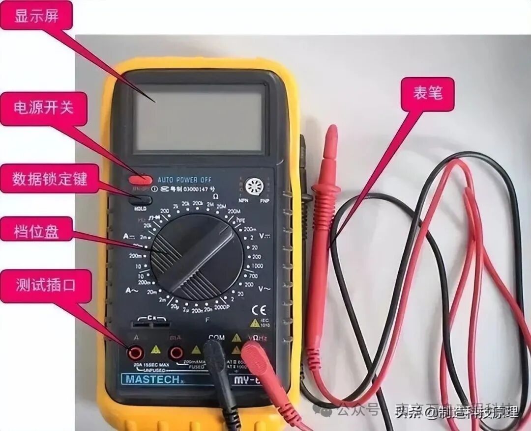
 Multimeter Usage Mnemonics
Check the range before measuring; do not measure without checking.
Do not change the range while measuring; switch to the off position after measuring.
The dial should be level, and the reading must be aligned correctly.
The range must be appropriate, and the reading should be aligned correctly.
Measure resistance (R) without power; discharge before measuring capacitance (C).
Set to zero before measuring resistance; adjust to zero when changing ranges.
Remember that black is negative; the black lead connects to + inside the meter.
For current (I) measurement, connect in series; for voltage (U), connect in parallel.
Do not reverse polarity; develop a habit of using one hand.
01Safety Level Standards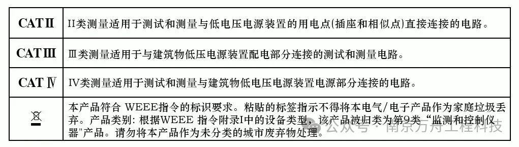 02Measurement Category Classification
The measurement categories are classified according to IEC standards. CAT I is suitable for low-voltage electronic circuits, such as PCB measurements. CAT IV is suitable for high-risk environments like outdoor power grids and transformer inputs. For measuring power grid sources, use equipment and probe components rated for measurement categories III or IV.
03Safety Operating Requirements
The insulation resistance measured between all circuits of the instrument and the reference test “ground” should not be less than 5MΩ when a 500V DC voltage is applied. During dielectric strength testing, the instrument should withstand an AC voltage of 50Hz practical sine wave for 1 minute without breakdown or arcing. When measuring power grid sources, the rated value of the probe components should not be less than the voltage of the circuit being measured.
04International Electrical Symbols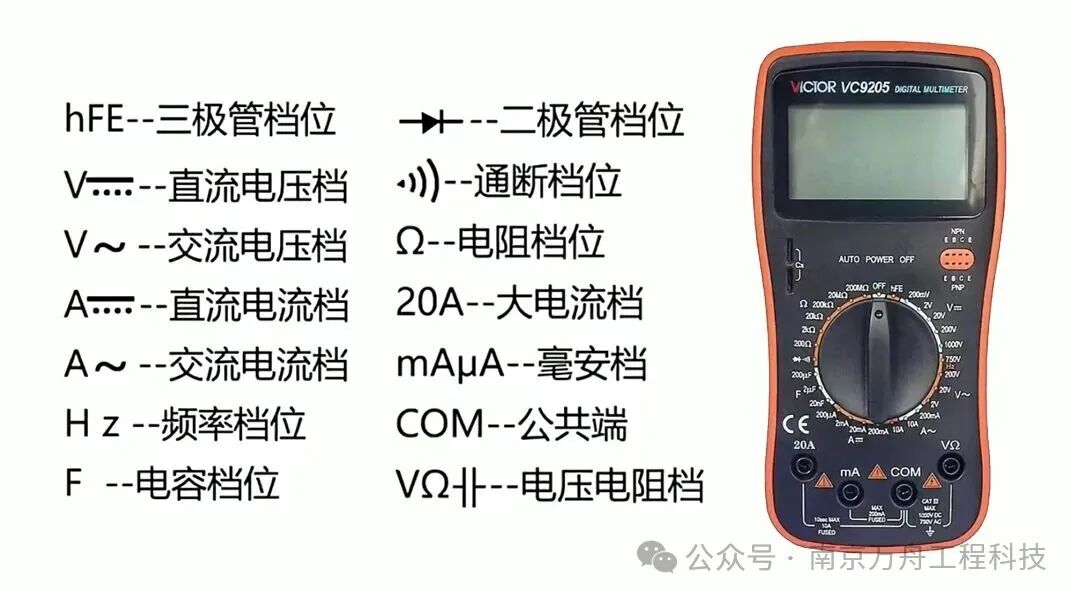 05Basic Electrical Quantity Symbols
The symbol for DC voltage is “V” with a horizontal line and a dashed line underneath. The symbol for AC voltage is “V” with a wavy line underneath. The symbol for DC current is “A” with a horizontal line and a dashed line underneath. The symbol for AC current is “A” with a wavy line underneath. The symbol for resistance is “Ω”. The symbol for capacitance is “F”.
06Function Symbols
The symbol for diode measurement is a triangle with a horizontal line and a vertical line. The symbol for the buzzer function is a sound wave pattern. The symbol for transistor gain measurement is “HFE”. The symbol for frequency measurement is “HZ”. The symbol for power off is “OFF”.
07Terminal and Display Screen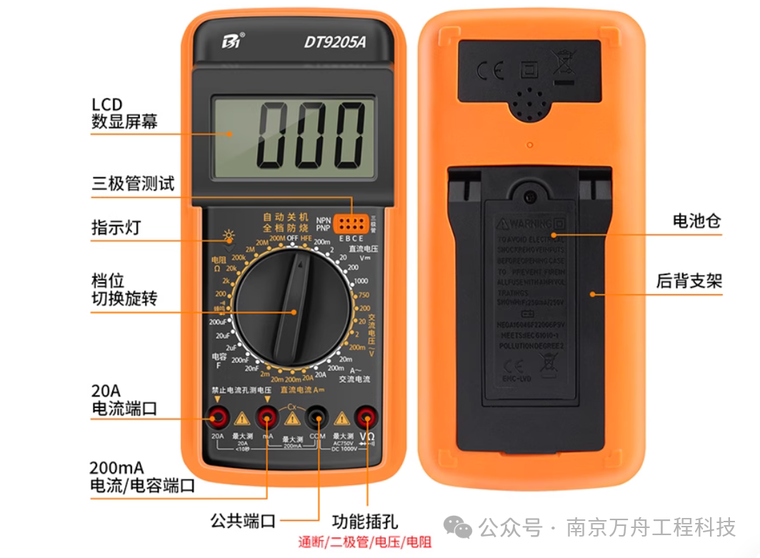 08Terminal Types and Uses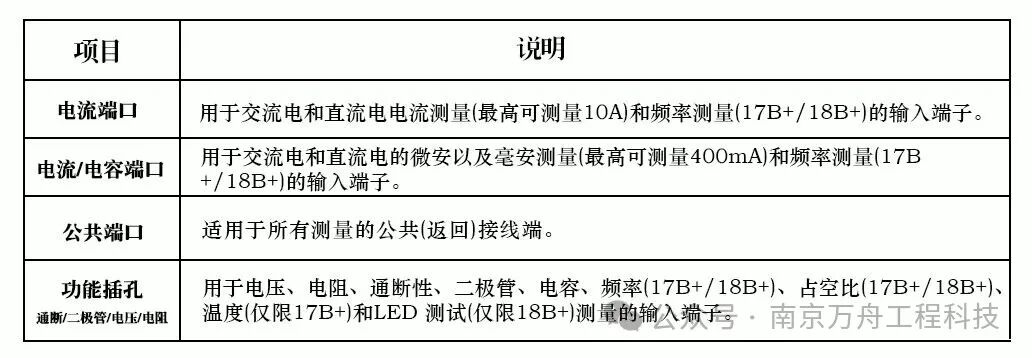
The COM terminal is the common terminal and should be connected to the black probe. For voltage and resistance measurements, the red probe connects to the socket marked “VΩ”. For small current (μA, mA) measurements, use the corresponding marked socket. For 10A large current measurements, insert into the dedicated 10A socket.
09Display Screen Symbol Meanings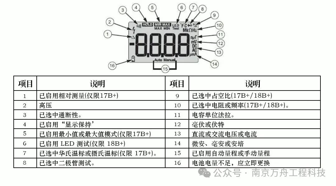
The numbers and units displayed on the screen represent the measurement value and range. For DC measurements, “DC” or the corresponding quantity symbol is displayed. For AC measurements, “AC” or the corresponding quantity symbol is displayed. In case of overload, a specific symbol or “OL” is displayed.
Range Selection and Measurement Methods
Voltage Measurement
Select the range corresponding to the voltage symbol. For AC voltage, select the “V~” range; for DC voltage, select the “V=” range. During measurement, the instrument should be connected in parallel across the circuit being measured. If the value range is uncertain, start with the maximum range and gradually decrease to the appropriate range.
Current Measurement
Select the range corresponding to the current symbol. For AC current, select the “A~” range; for DC current, select the “A=” range. During measurement, the instrument should be connected in series in the circuit being measured. Choose a range that keeps the pointer above two-thirds of the scale (for analog meters).
Resistance Measurement
Select the appropriate range marked with “Ω”. Before measuring, short the probes and adjust the zero adjuster to bring the pointer back to zero (for analog meters). Each time the range is changed, zero adjustment is required. The resistance in the circuit must be powered off. If there is a capacitor in the circuit, it should be discharged first.
Diode Measurement
Select the diode-specific symbol range. When the red probe is connected to the positive terminal of the diode and the black probe to the negative terminal, it displays the forward voltage drop. When connected in reverse, it displays “OL” or infinity. The greater the difference in resistance between forward and reverse, the better.
Reference Standards:
GB/T 42125.1—XXXX “Safety Requirements for Electrical Equipment for Measurement, Control and Laboratory Use”
IEC 61010-031:2022 “Safety Requirements for Electrical Equipment for Measurement, Control and Laboratory Use – Part 031”
JJG 124—2005 “Verification Regulations for Ammeters, Voltmeters, Power Meters, and Ohmmeters”
IEC 61010-2-030:2023 “Safety Requirements for Electrical Equipment for Measurement, Control and Laboratory Use – Part 2-030”