
Common Multimeters
Correct Usage
Be cautious with electrical safety.
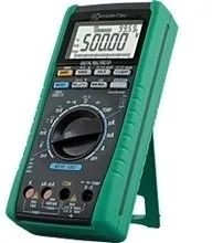
Common multimeters include analog and digital types: the analog multimeter is a multifunctional measuring instrument based on a mechanical dial, with values indicated by a needle on the dial; the digital multimeter displays values directly in numerical form on a liquid crystal screen and often includes voice prompt functions.
By appearance, there are desktop, clamp, handheld, and pocket types.
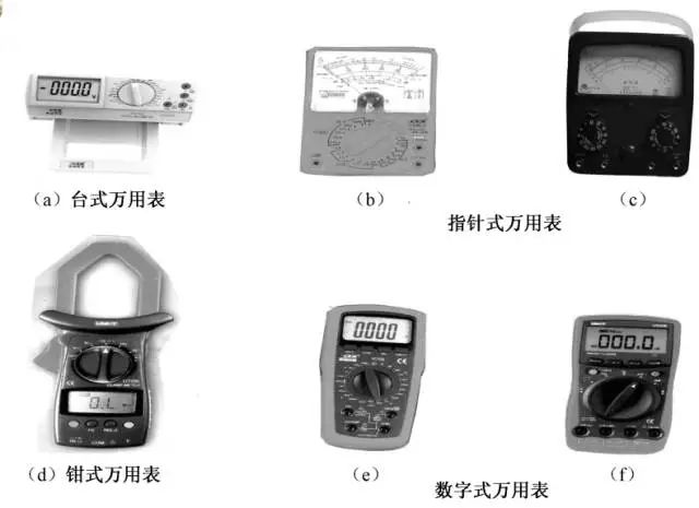
Accuracy Comparison
The reading accuracy of analog multimeters is slightly lower than that of digital multimeters, but the movement of the needle is more intuitive and obvious, and its speed and amplitude can sometimes objectively reflect the size and direction of the measured value.
Digital instruments have high sensitivity, accuracy, clear display, strong overload capacity, are easy to carry, and are simpler to use.
Analog Multimeter
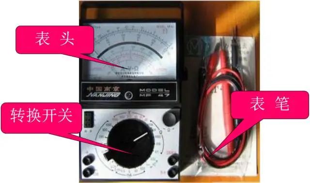
There are many types of analog multimeters, but their basic structure is similar. The structure of an analog multimeter mainly consists of the display unit, a switch (also known as a selection switch), and measurement circuits.
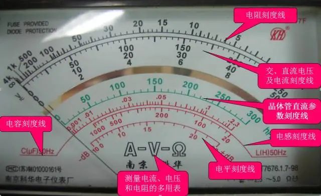
Display Unit: This is the measurement display device; the display unit of the multimeter is essentially a sensitive ammeter.
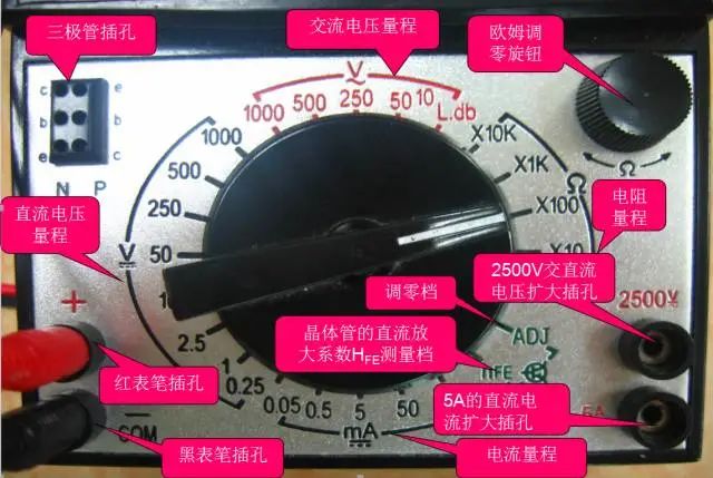
Switch: Selects the type and range (or multiplier) of the measured quantity.
Measurement Circuit: Converts different types and sizes of measured quantities into direct current that the display unit can accept.
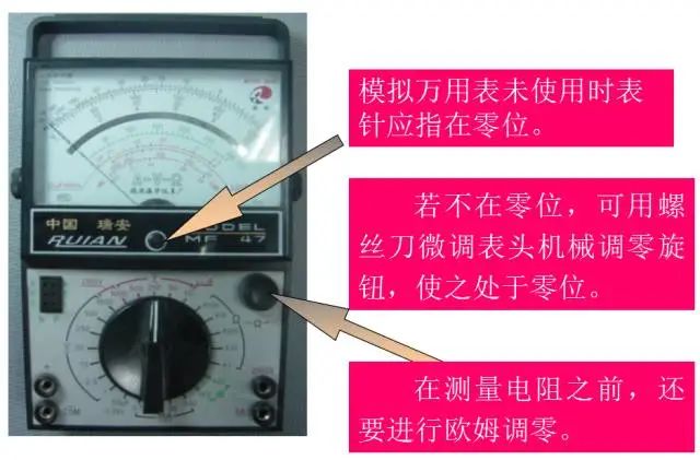
Usage Method
When using:
(1) It must be placed horizontally to avoid errors.
(2) Do not collide with hard objects or drop it on the ground.
(3) Do not touch the metal parts of the test leads with your hands.
(4) When measuring a certain quantity, do not switch ranges while measuring, especially when measuring high voltage, as this may damage the multimeter.
If you need to change the range, disconnect the test leads first, then change the range before measuring.
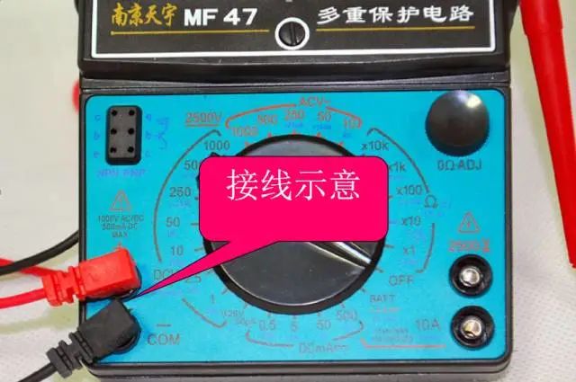
Correct Wiring:
1. Connect the red test lead to the “+” polarity socket, and the black test lead to the “—” or “*” or “COM” polarity socket.
2. When measuring DC, pay attention to the positive and negative polarities to avoid reversing the needle.
3. When measuring current, the instrument should be connected in series with the circuit being measured; when measuring voltage, the instrument should be connected in parallel across the circuit.
4. When measuring transistors, remember that the red test lead should connect to the negative terminal of the internal battery, and the black test lead should connect to the positive terminal of the internal battery.
Correctly Selecting Measurement Ranges:
1. When measuring voltage, the switch should be set to the corresponding voltage range; when measuring current, it should be set to the corresponding current range, etc.
2. When selecting current or voltage ranges, it is best to keep the needle above two-thirds of the scale; when selecting resistance ranges, it is best to keep the needle in the middle of the scale.
3. When unsure of the range of the measured value, first set the switch to the corresponding maximum range, then gradually reduce it to an appropriate range based on the needle’s deflection.
After Use:
(1) After using the multimeter, if there is no empty range, set the range switch to the highest AC voltage range; if there is an empty range (“*” or “OFF”), set it to that range.
(2) If the multimeter will not be used for a long time, remove the battery to prevent leakage of the battery electrolyte from corroding the internal circuit.
Digital Multimeter
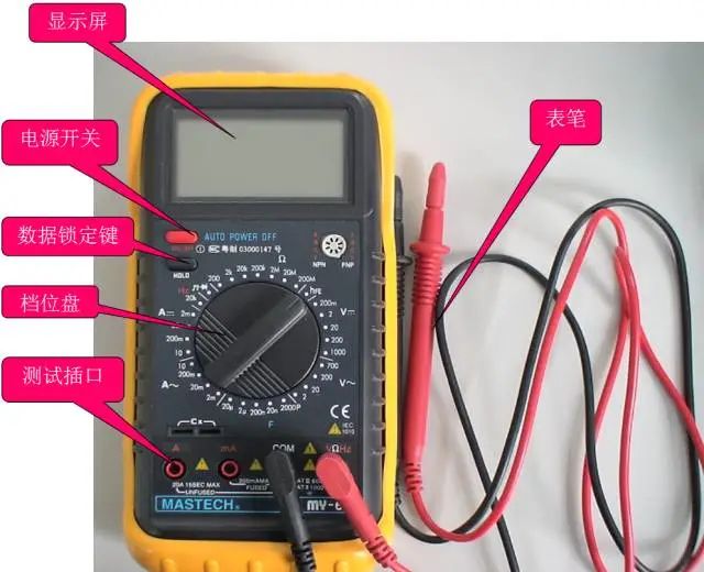
Useful Methods
1. Determine if a line or device is live.
The AC voltage range is very sensitive, and even a small induced voltage nearby can display. Based on this feature, it can be used as a voltage tester.
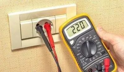
Usage: Set the multimeter to AC20V, keep the black test lead floating, and touch the red test lead to the line or device being tested. The multimeter will display; if the displayed number is between a few volts to a dozen volts (different multimeters will show different values), it indicates that the line or device is live; if it displays zero or a very small number, it indicates that the line or device is not live.
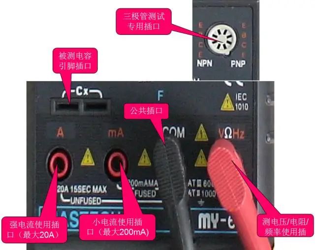
2. Distinguish whether the power line is live or neutral.
First method: Use the above method to judge: the line with a higher displayed number is the live line, and the line with a lower displayed number is the neutral line. This method requires contact with the line or device being measured. Second method: No contact is needed. Set the multimeter to AC2V, keep the black test lead floating, and slide the tip of the red test lead along the line gently. If the display shows a few volts, it indicates that the line is live; if it shows only a few tenths of a volt or even less, it indicates that the line is neutral. This method does not require direct contact with the line, making it safe and convenient.
3. Locate breaks in cables.
When there is a break in the cable, the traditional method is to use the multimeter’s resistance range to find the break segment by segment, which not only wastes time but can also significantly damage the cable’s insulation. Utilizing the sensitivity of the digital multimeter can quickly find the break point in the cable.
First, use the resistance range to determine which core wire of the cable has an open circuit. Then connect one end of the broken core wire to AC220V, and set the multimeter to AC2V. Keep the black test lead floating, and slide the tip of the red test lead along the line gently. If the display shows a few volts or a few tenths of a volt (depending on the cable), if at some point the display suddenly drops significantly, note this position: generally, the break point is between 10 to 20 cm before this position.
This method can also be used to locate the open circuit points of faulty electric blankets and other resistance wires.
4. Measure frequency.
For UPS power supplies, the stability of the output voltage is an important parameter, and the output frequency is also very important. However, the frequency range of the digital multimeter cannot be used for direct measurement because it can only handle very low voltages.
At this point, you can connect a 220V/6V or 220V/4V step-down transformer to the output of the UPS power supply to reduce the voltage without changing the frequency of the power supply, and then connect the frequency range to the output of the transformer to measure the frequency of the UPS power supply.
Correctly using the multimeter can quickly and accurately determine the fault location and prevent damage to electrical equipment and the multimeter itself. Learn these practical techniques to use the multimeter correctly and effectively.