Oscilloscope probes are widely used in electronic measurements, such as debugging complex electronic circuits, measuring the signal integrity of high-speed serial bus signals, and characterizing high-voltage power electronic devices. The probes and accessories used largely determine the measurement accuracy and the safety of the operator.
In general, the probe product range includes high-quality active and passive oscilloscope probes, power integrity probes, multi-channel power probes, high-voltage probes, current probes, and EMC near-field probes. Besides the diverse specifications, oscilloscope probes must also be reliable and easy to use.
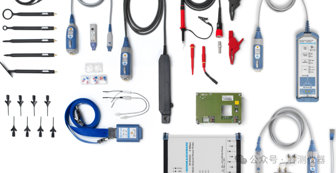 1. What is an oscilloscope probe?Oscilloscope probes are devices used to connect a signal source (usually a test point on a circuit) to an oscilloscope, thus achieving an electrical connection through a physical link. There are various types of probes; depending on the signal source and measurement type, probes can be simple wires (like passive probes) or include precision active differential probes—these probes use amplifiers to keep the probe input capacitance at a very low level, thereby minimizing the probe’s impact on the signal being measured.2. How to choose the right probe?
When selecting the appropriate probe, the first step is to analyze the measurement task. Is the circuit under test grounded (do you need to use a single-ended probe or a differential probe)? What is the maximum frequency of the signal (what bandwidth is required)? What is the maximum input voltage likely to be?
Differential or single-ended measurement
Differential probes are suitable for the following situations: when the circuit under test is not grounded, measuring the voltage of switch-mode power supplies, or low-noise measurements between differential signals. While there is no reason to suggest that differential probes cannot be used for grounded circuits, single-ended probes perform better for such applications: they have higher input impedance, lower input capacitance, and greater dynamic range.
Bandwidth and rise time
When selecting a probe, bandwidth is one of the most important parameters. Bandwidth determines the actual maximum frequency that the probe can accurately measure; at the specified maximum frequency, the displayed signal strength will be more than 3 dB lower than the actual strength (approximately a 30% reduction). To ensure accurate signal display, the maximum frequency of both the oscilloscope and the probe must be significantly higher than the maximum frequency of the signal under test. When measuring digital signals, the measurement bandwidth should be 3 to 5 times the clock frequency; using 3 times the bandwidth is sufficient when debugging digital designs. For consistency testing of digital interfaces, the bandwidth must be 5 times the clock frequency.
When measuring fast-rising signals (for example, characterizing switch-mode power supplies), a steep slope will appear on the oscilloscope display, making the rise time of the oscilloscope and probe very important. To ensure accurate measurements, the rise time of the oscilloscope and probe should be less than one-fifth to one-third of the rise time of the pulse being measured.
Dynamic range
The dynamic range of a probe determines the maximum measurable input voltage. The dynamic range is specified for DC voltage and typically decreases with increasing signal frequency. There is also a difference between the common-mode and differential-mode dynamic ranges of differential probes. The common-mode dynamic range specifies the effective input voltage range of a single differential input and is measured against a grounded reference. The differential-mode dynamic range specifies the maximum measurable input differential voltage.
To accurately measure large amplitude signals with fast rise/fall times, sufficient dynamic range must be provided at high measurement frequencies. When measuring the residual ripple of a DC switch-mode power supply, it is also necessary to measure very weak signals with a large DC component. To achieve full analog-to-digital converter resolution, modern probes offer options to feed in DC offsets.
When using high-voltage probes, the safety of the operator is a primary consideration. Therefore, high-voltage probes have special insulation and other protective mechanisms to prevent accidental contact. The characteristics of these probes include maximum grounded voltage and measurement classification. Measurement classification defines the measurement environment in which the operator is protected. Probes are only used in the defined measurement category environment.
Load of the device under test
The measurement system must not overload the circuit under test to prevent signal degradation and ensure that the functionality of the device under test is not damaged. Using probes with high input impedance and low input capacitance is crucial. The resulting input impedance largely depends on frequency and is usually below 500 Ω at the cutoff frequency of the probe.
Passive probes typically have an input impedance of 10 MΩ, with input capacitance generally exceeding 10 pF. Active probes usually have an input capacitance of about 1 pF. When connecting to the device under test, it is essential to choose the appropriate probe accessories. Long leads and wires can increase capacitance and inductance, reduce the maximum measurement bandwidth, and lead to excessive overshoot and oscillation effects on pulse edges.
Wide range of functions and probe accessories
In addition to performance parameters, supplementary probe functions that simplify daily tasks should also be considered. Many active probes from Rohde & Schwarz include integrated digital voltmeters or micro-control buttons. The voltmeter can be used to view voltage without changing any connections. The micro-control buttons can be configured to directly control the oscilloscope through the probe.
Various accessories facilitate flexible connections to test points, making the operator’s daily work easier and helping to prevent measurement errors. Available accessories include rigid and spring probe tips, point measurement kits, adapters, and extension leads. Rohde & Schwarz provides comprehensive accessories for all probes.
3. What is a power integrity probe?Power integrity probes are specifically designed to measure small AC components on DC power paths. The attenuation factor of power integrity probes is typically 1:1, resulting in very low measurement noise. Some power integrity probes offer built-in bias of up to ±60 V, allowing for optimal use of the oscilloscope’s vertical sensitivity (utilizing more bits of the oscilloscope’s analog-to-digital converter), thus achieving more accurate and lower noise measurements. Additionally, using bias measurements differs from AC coupling or isolation devices, allowing for intuitive display of DC components and drift. Power integrity probes provide bandwidths of up to 2 GHz and have slow roll-off characteristics that help capture high-frequency transient signals and coupled signals. High input impedance (typically 50 KΩ) minimizes interference with the signals on the measured power path.4. How does a differential probe work?Differential probes can measure the difference in signal levels between any two measurement points. Single-ended probes can measure the difference in signal levels between a single measurement point and ground potential. Differential probes are particularly common for measuring high-frequency signals or signals with very low amplitudes (close to the noise floor). Differential probes require the use of differential amplifiers to convert the difference between the two signals into a voltage that can be sent to the (single-ended) oscilloscope input.5. How to choose power testing probes?
When evaluating power electronics, various measurement scenarios are typically involved:
- Measuring small voltages in large common-mode voltages
- Measuring different voltage levels at different potentials simultaneously
- Measuring fast rise/fall times, especially for wide bandgap materials (WBG) like GaN and SiC
- Floating measurements of multiple signal channels
- Current measurements
In principle, differential high-voltage probes are very suitable for these measurements. The R&S®RT-ZHD high-voltage differential probe offers a bandwidth of up to 200 MHz across a wide frequency range and an excellent common-mode rejection ratio (CMRR), making it ideal for measuring fast-switching semiconductors. Extremely low additive noise enables high-quality measurements. The signal path gain accuracy of the R&S®RT-ZHD probe is up to 0.5%, and it integrates a DC voltmeter (R&S®ProbeMeter) with an accuracy of 0.1%, achieving outstanding measurement accuracy superior to competitors. The drift is very low, eliminating the need for periodic calibration during measurements. To measure ripple voltage on DC links, large offset voltages must be compensated to ensure measurements are made with high vertical sensitivity. The R&S®RT-ZHD probe integrates offset circuits that provide offset voltage ranges unaffected by the oscilloscope’s vertical settings and probe attenuation factors. This allows for measuring very small ripple voltages on large DC link voltages without sacrificing sensitivity.
Typical measurement parameters for evaluating power electronics include:
- Power consumption / efficiency / standby power
- Power quality / power factor
- Voltage and current waveform analysis
- Ripple
- Inrush current / transients
- Startup / shutdown characteristics
- Load regulation
- Pulse width modulation (PWM) analysis
- EMC / harmonic analysis

Scan the QR code

Follow us
If you have questions, contact us|Instrument rental Instrument sales Instrument maintenance
Service hotline|13912605605/18964059485
(Source: Internet)