
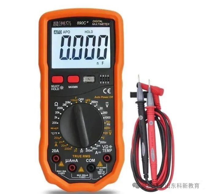

01. Correct Use of the Multimeter
To use the multimeter correctly, familiarize yourself with the dial. Adjust the two zero position regulators gently. Choose the correct binding posts, and insert the red and black probes into the correct holes.
Turn the switch to the correct position; ensure the range is set appropriately for accurate readings. Look at the scale line directly above the surface for an accurate reading.
After measurement, switch the probes back to the high voltage range. Regularly check the battery inside the meter, as deterioration can cause electrolyte leakage. Store the instrument in a good environment, free from vibration, humidity, and weak magnetic fields.
02. Correct Use of the Ohm Range on the Multimeter
To correctly use the ohm range, be aware of eight essential points. Ensure the battery voltage is sufficient, and the circuit being measured is de-energized. Select the appropriate range, positioning the needle in the middle of the scale.
Each time you change the range, you must recalibrate the resistance to zero. Ensure good contact at the test points, and do not touch the probe ends with your hands. Measure continuity in the circuit with a range of thousands of ohms.
Test the diode components with different resistance values for different ranges. Measure the transformer windings with caution, as touching them may cause an electric shock.
03. Precautions When Measuring Voltage with the Multimeter
When measuring voltage with the multimeter, be aware of eight precautions. Know the internal resistance of the meter, and ensure supervision is present. The meter should be connected in parallel to the live circuit, and do not change the range while energized.
When measuring DC voltage, be clear about the polarity of the circuit. For AC voltage measurements, do not disconnect the power supply during the test. When testing high voltage (in kilovolts), use specialized probes. Induced voltage measurements can vary significantly across different ranges.
04. Measuring DC Current with the Multimeter
To measure current with the multimeter, set the switch to the milliamp range, and determine the circuit’s polarity. The meter must be connected in series with the circuit. Choose a range that is appropriate to minimize the impact on the circuit.
05. Identifying the Ends of a Three-Phase Motor Stator Using DC Method
For three-phase motor windings, use the DC method to identify the ends. Set the multimeter to the milliamp range, using a dry cell for the DC power source. Connect one winding to the meter and touch the other winding to the battery.
When powered, the needle should move; if it moves in the opposite direction, that is the start. If not, swap the connections, and check the remaining winding using the same method.
06. Using Residual Magnetism to Identify the Ends of a Three-Phase Motor Stator
For motors that have been operated, use the residual magnetism method to identify the ends. After marking the ends of the three-phase windings, connect them in parallel. Set the multimeter to the milliamp range and connect to the common point.
Slowly turn the motor shaft while observing the meter needle. If the needle does not fluctuate significantly, the three ends are connected. If the needle swings left and right, it indicates two ends are connected to one end.
Swap the ends of one winding and repeat the measurement until the needle stabilizes, indicating the ends are correctly identified.
07. Using Loop Current to Identify the Ends of a Three-Phase Motor Stator
For motors that have been operated, use the loop current method to identify the ends. Connect the three-phase windings in a triangle configuration. Set the multimeter to the milliamp range and connect in series with the three-phase windings.
Evenly rotate the motor shaft while observing the meter needle. If the needle does not fluctuate significantly, the ends are connected. If the needle fluctuates greatly, it indicates that one of the winding ends is reversed. The two connection points and wire ends represent the start and end.
08. Measuring the Speed of a Three-Phase Motor Using the Multimeter
To measure the speed of a three-phase motor, use the multimeter. Open the motor junction box and remove the connecting terminal links. Set the multimeter to the milliamp range and connect to any one phase winding.
Rotate the rotor for one full turn while observing the needle. A two-pole motor will indicate one swing, while a four-pole motor will indicate two swings, corresponding to synchronous speeds of 3000 RPM and 1500 RPM, respectively. Continue this method to deduce the speed, noting that the actual speed may be slightly lower than the synchronous speed.
09. Testing the Grounding Resistance of Household Ground Protection Lines
To test the grounding resistance of household grounding wires, set the multimeter to the voltage range, connecting a kilowatt electric stove to the phase and neutral. Measure the voltage at the stove terminal and calculate the working current.
Reconnect the stove to the ground wire, and measure the voltage again. The difference in voltage readings divided by the working current gives the grounding resistance value, with an approximate error of 5%.
10. Identifying the Phase and Neutral Wires of a Low Voltage AC Power Supply
In a low voltage three-phase four-wire system, identify the phase and neutral wires. Set the multimeter to the voltage range, selecting 250V AC, connect one probe to the ground, and touch the other probe to the power wire.
If the needle deflects significantly, you are touching the phase wire. If the needle does not move or only slightly deflects, you are touching the neutral wire.
11. Testing the Polarity and Integrity of a Diode
To test the polarity of a diode, set the multimeter to the kilo-ohm range. If the resistance is less than a thousand ohms, the diode is forward-biased. Connect the black probe to the anode and the red probe to the cathode. If the resistance is several thousand ohms, the diode is reverse-biased. Connect the red probe to the anode and the black probe to the cathode.
To determine the diode’s integrity, set the multimeter to the kilo-ohm range. A large difference between forward and reverse resistance indicates good condition. If the values are close, the diode is likely faulty. If both readings are zero, it indicates a short circuit between the terminals. If both readings are infinite, the diode is open.
12. Testing the Integrity of High-Voltage Silicon Rectifiers
To check the integrity of silicon rectifiers, set the multimeter to the voltage range. Connect the silicon rectifier in series with the multimeter, applying 220V AC. Set the range to 250V DC, connecting the rectifier in the forward direction.
If the reading is greater than 30 volts, it is considered functional; if the needle does not move, there is a fault. For the 250V AC range, a reading of 220 indicates a short circuit. If the needle does not move and the reading is zero, the rectifier is open.
13. Testing Capacitor Integrity
To test the integrity of microfarad capacitors, set the multimeter to the kilo-ohm range and connect the probes to the terminals. The needle should swing once; the larger the swing, the better the capacitor.
If the needle does not move, the capacitor is open. If the needle drops to zero without returning, the capacitor has shorted.
14. Using a Digital Multimeter to Test the Quality of Electrolytic Capacitors
To test the quality of electrolytic capacitors, set the digital multimeter to the buzzer mode. Connect the probes to the positive and negative terminals. A brief beep indicates a good capacitor; if the beep continues, it indicates a short circuit. If there is no sound, the capacitor is open.
15. Safety Procedures When Using Clamp Meters
When using a clamp meter, remember the safety procedures. Testing on high-voltage circuits must be done by two people. Ensure the potential of the wire being tested does not exceed the clamp meter’s voltage level.
Always wear gloves and stand on an insulated platform. Maintain a safe distance from any charged objects. When measuring low-voltage bus currents, ensure proper insulation and protection. Do not use clamp meters on poorly insulated or bare wires.
16. Correct Use of Clamp Meters
When using clamp meters, select the appropriate model and specifications. Start with the maximum range for rough measurements, and choose suitable range settings. Ensure the wire is centered in the clamp jaws, with the static and dynamic cores aligned.
Once the clamp is closed around the wire, do not change the range while powered. Use clamp meters separately for current and voltage measurements. Do not insert both wires of a lighting circuit into the clamp jaws simultaneously. Always set the range to maximum after each test.
17. Techniques for Measuring Three-Phase Three-Wire Current with Clamp Meters
To measure three-phase three-wire current with a clamp meter, apply Kirchhoff’s laws. Insert one wire into the clamp to read the current for that phase.
Insert two wires into the clamp to read the current for the third phase. If all three wires are clamped, the balanced load will indicate zero reading.
18. Techniques for Measuring Small AC Currents with Clamp Meters
To measure small AC currents with a clamp meter, wrap the insulated wire around the clamp core. Divide the reading by the number of turns plus one to get the actual current value.
19. Detecting Phase Loss in a Three-Phase Resistance Furnace
To detect phase loss in a three-phase resistance furnace, use a clamp meter. If two phase wires show current values below the rated current and one phase shows zero current, that phase’s resistance wire is burned out.
20. Locating Short Circuit Ground Faults in Low Voltage Distribution Lines
In long low voltage distribution lines, locating short circuit ground points can be difficult. Connect the faulty phase wire to the electric stove, and connect the single control switch to the power supply. Use a clamp meter to measure the current in segments of the line.
The point where the current is absent indicates the short circuit ground fault.
21. Testing Thyristor Rectifiers
To test thyristor rectifiers, use a clamp meter. Connect the anode to the clamp and observe the current reading on the meter. If the reading is zero, the component is not functioning.
For three-phase components, the current values should be roughly balanced for normal operation. Severe imbalance indicates phase shifting inconsistency. Faults in the AC portion may indicate a missing phase in the rectifier transformer.
22. Detecting User Phase Theft
If a user’s single-phase energy meter records less or no consumption, use a clamp meter to test the energy meter’s position before or after.
Clamp the phase wire and neutral wire; if the meter shows a non-zero reading, it indicates phase theft, typically in a one-phase-to-ground configuration.
23. Safety Procedures When Using Insulation Resistance Meters
When using insulation resistance meters, adhere to safety protocols. Measurements on high-voltage equipment must be performed by two individuals. Ensure the equipment is completely powered down and properly discharged.
When measuring the insulation of circuits, obtain permission from the other party. Both circuits must be powered down, and measurements should not be taken during thunderstorms. Maintain a safe distance when measuring near energized equipment.
Ensure adequate safety distance and supervision to prevent electric shock.
24. Correct Use of Insulation Resistance Meters
When using insulation resistance meters, select the appropriate voltage level. Ensure the equipment is completely powered down and thoroughly discharged before testing. Clean the surface of the equipment to remove any dirt.
Position the meter away from electric and magnetic fields. Place it horizontally without tilting, and perform both open and short circuit tests. Use two-color single-core soft leads, ensuring they do not tangle and are properly insulated.
Clearly identify the terminal connections and ensure correct wiring. Turn the handle clockwise to gradually reach a constant speed. There is no fixed time for testing; stabilize the needle and record the reading.
25. Important Notes When Using Insulation Resistance Meters
When using insulation resistance meters, remember eight key points. Do not touch the terminal connections during the testing period. Avoid wiping the glass of the meter during the measurement process.
When measuring equipment insulation to ground, connect the ground terminal to the casing. When testing capacitors, connect the ground terminal to the positive terminal.
When measuring equipment on the same platform, it is best to use the same meter. Record the temperature during insulation testing. Avoid measuring resistances below 100K ohms, and do not use the meter for general purposes.
26. Connecting Diodes in Series to Prevent Equipment Discharge to Insulation Resistance Meters
To prevent discharge to insulation resistance meters, connect a diode in series with the meter. This will help avoid discharge current when measuring capacitive equipment. This will stabilize the needle’s movement, ensuring accurate readings. After measurement, stop turning the handle to prevent damage to the meter.
27. Increasing the Voltage Level of Insulation Resistance Meters
For low-voltage insulation resistance meters, connect them in series to increase the voltage. The voltage level will add up, and the insulation resistance readings will be more accurate.
28. Insulation Absorption Ratio of Power Transformers
The quality of transformer insulation can be determined using an insulation resistance meter. At room temperature around twenty degrees, start counting from the time of measurement: after fifteen seconds, observe the reading, and stabilize after elapsed seconds.
The ratio of the two insulation resistance values is called the insulation absorption ratio. A value greater than 1.3 is good; less than 1.3 indicates moisture.
29. Quickly Assessing the Integrity of Low Voltage Motors
To assess the integrity of low voltage motors, open the junction box for inspection. Use an insulation resistance meter to measure the minimum insulation resistance value; at thirty-five degrees, the baseline is eight, decreasing by half for every ten degrees increase. For every ten degrees decrease, double the reading to determine if it is acceptable.
Set the multimeter to the milliamp range, and use the star connection method. Connect the probes to any two phase heads and slowly rotate the shaft. If the needle swings significantly three times, the motor is good; otherwise, it is faulty.
30. Testing the Integrity of High Voltage Silicon Rectifiers with Insulation Resistance Meters
To test the integrity of high voltage silicon rectifiers, use an insulation resistance meter. Connect the two leads to the silicon rectifier terminals. Measure the resistance in both forward and reverse directions; a significant difference in the values indicates good condition.
If the two readings are very close, the rectifier is likely faulty. If both readings are infinite, it indicates an open circuit. If both readings are close to zero, it indicates a short circuit within the rectifier.
31. Testing the Integrity of Self-Ballasted High Voltage Mercury Lamps
To test the integrity of high voltage mercury lamps, use a kilovolt insulation resistance meter. Connect the two leads to the lamp terminals, and slowly increase the speed of the test.
If the reading is less than half a megaohm, it indicates a good lamp; if the lamp does not light, the reading is zero, indicating an internal short circuit. If the needle indicates infinity, it indicates an open circuit fault.
32. Testing the Quality of Fluorescent Tubes with Insulation Resistance Meters
To test the quality of fluorescent tubes, use a kilovolt insulation resistance meter. Set the multimeter to the voltage range, selecting 500V DC. Connect the multimeter in parallel, ensuring the polarity is correct.
Connect the two leads to the ends of the fluorescent tube. If the lamp lights at rated speed, it is normal if the voltage is below 300V. If it lights dimly, it indicates aging above 300V. If the lamp does not flash, it indicates that the tube is damaged.
33. Testing the Starter of a Fluorescent Lamp with Insulation Resistance Meters
To test the starter of a fluorescent lamp, use an insulation resistance meter. Connect the two leads to the starter terminals. Slowly and gently move the meter handle; if the neon bulb flashes red, the starter is functioning well; otherwise, it is faulty.
Source: This article is adapted from the internet, and the copyright belongs to the original author. If there are any copyright issues, please contact us for removal. Thank you!

Scan to Follow
WeChat ID|13615417996
Follow the QR code on the left for free access
[Siemens Reference Materials]