
In daily electrical maintenance or motor inspection work, determining the condition of a three-phase motor is a crucial skill. The multimeter, known as the “magic tool” for electrical maintenance, plays a significant role in this process. So, which setting should we use on the multimeter to assess the condition of a three-phase motor? Hello everyone, I am Da Biao Ge, and today we will take a look.
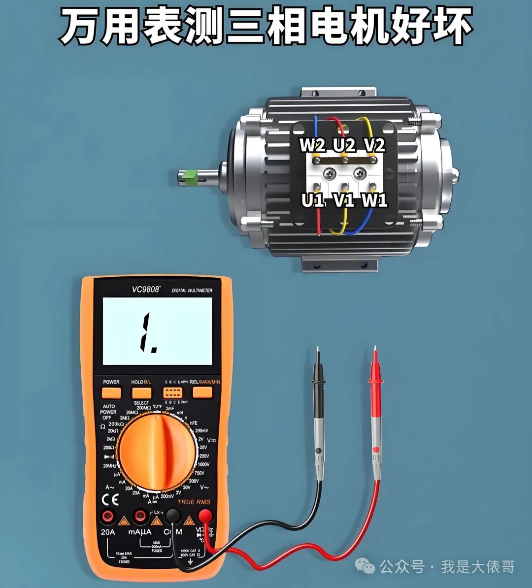
Basic Information on Three-Phase Motors
Three-phase motors are widely used in industrial and daily life applications, such as various machinery in factories and some large appliances at home. To determine their condition, we can approach it from several aspects, and different settings on the multimeter can help us test different parameters.
Resistance Setting (Ω)
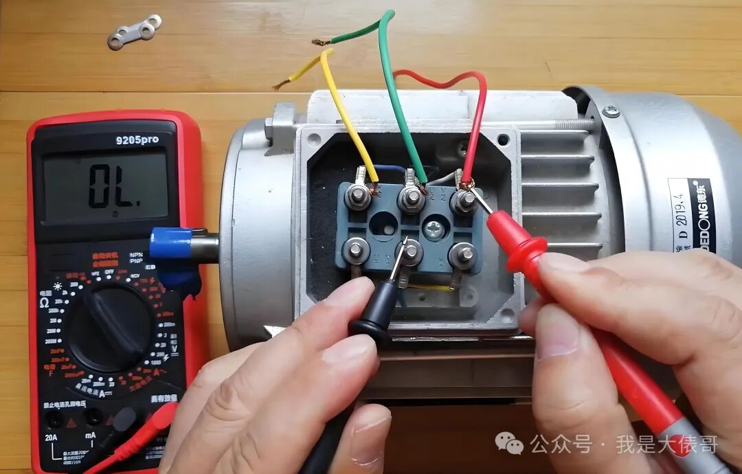
Winding Continuity Test
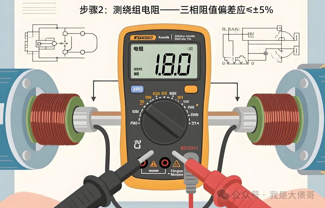
The resistance setting on the multimeter is the most commonly used. We set the multimeter to an appropriate resistance range; generally, the resistance of motor windings is not very high, ranging from a few hundred ohms to a few ohms. Therefore, we can start with a moderate range, such as the 200Ω setting. Then, we measure the resistance between the three windings of the three-phase motor, specifically U1-U2, V1-V2, and W1-W2. Under normal circumstances, the resistance values of these three windings should be balanced, meaning they should not differ significantly. If the resistance of one winding is infinite, it indicates that this winding may be open-circuited; if the resistance is zero, it may indicate a short circuit. According to electrical maintenance experts, winding open circuits and short circuits account for about 30% of motor failures.
Winding Insulation Test
Set the multimeter to the 2 MΩ range, disconnect the motor connection, and measure the insulation resistance between the windings.The insulation resistance between U-V, V-W, and W-U should be >1MΩ.
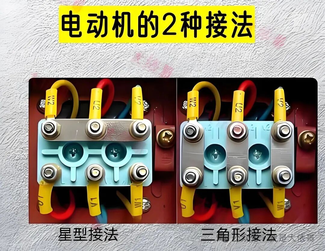
Three-phase motors can be connected in two ways: star connection and delta connection. In fact, without disconnecting the connection, we can measure the three resistance values and, based on the three-phase balance principle, determine if the insulation between the three windings is good. Measurement method: If it is a star connection, measure the resistance between U1, V1, and W1 with respect to the neutral point to see if they are balanced. If it is a delta connection, measure the resistance between U1, V1, and W1; if the resistance values are the same or close, it indicates good insulation between the three windings.

Ground Insulation Test
In addition to measuring the resistance between the windings, we also need to measure the insulation resistance of the windings to ground. Set the multimeter to a high resistance range, such as 2 MΩ, then connect one probe to the motor winding and the other probe to the motor casing. Under normal circumstances, the insulation resistance should be in the megohm range. If the insulation resistance is very low, even close to zero, it indicates that the motor’s insulation may be damaged, posing a risk of leakage. Measurement method: Disconnect the motor connection and measure the insulation resistance between U1, V1, and W1 and the motor casing; infinite resistance is ideal, indicating excellent insulation, with the minimum requirement being insulation resistance >1MΩ (≥0.5MΩ in humid environments).
Voltage Setting (V)
Power Voltage Detection
When we suspect that the motor is not working due to a power issue, we can use the voltage setting on the multimeter. Set the multimeter to the appropriate AC voltage range; generally, the power voltage for three-phase motors is 380V, so we can select the AC 750V range. Use the probes to measure the line voltage of the three-phase power supply, specifically the voltage between U-V, V-W, and W-U. Under normal circumstances, the line voltage should be around 380V, allowing for some fluctuation. If the measured voltage deviates significantly, it may indicate a problem with the power supply.

Conclusion
From the above introduction, we understand that when testing the condition of a three-phase motor, the resistance and voltage settings are the two most commonly used settings on the multimeter. The resistance setting is primarily used to check the continuity and insulation of the motor windings, while the voltage setting is used to check whether the power voltage is normal. In practical operation, we should choose the appropriate setting based on the specific situation for measurement. By mastering these methods, I believe everyone will be more confident in testing and repairing three-phase motor faults. If you have any questions while using the multimeter to test the motor, feel free to leave a comment for discussion!