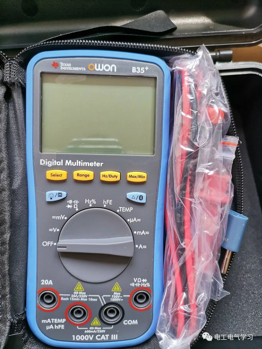
For multimeters, I believe that many electricians engaged in maintenance are no strangers to them. After all, it would be absurd to say that any electrician does not know how to use a multimeter. Although most electricians are familiar with the functions and usage of multimeters, it is crucial to pay attention to the proper selection of measurement ranges during actual use. Recently, a colleague from the neighboring unit was perplexed by this issue.
The story goes like this: A PLC, touch screen, and inverter-based automated production line at the neighboring unit has recently been experiencing intermittent automatic shutdowns. To find the cause of the malfunction, the colleagues there tested and secured the switching power supply, PLC, and various connectors in the electrical control system of the production line, but the fault persisted. They then used the multimeter to measure the various function buttons in the electrical control system in the “continuity buzzer” mode but found no abnormalities. They were left with no choice but to call in technicians from the electrical control system manufacturer.
However, to their surprise, the manufacturer’s technician arrived and, after measuring with the multimeter, simply replaced a “stop” button to easily resolve the fault. The colleague was greatly puzzled because he had previously measured the normally closed contact of that button, and at that time, the multimeter had indicated continuity with a beeping sound! Filled with doubts, the colleague asked the manufacturer technician for guidance. After observing the colleague’s measurement process, the technician pointed out the reason for the misjudgment: the colleague had selected the “continuity buzzer” mode on the multimeter, which defaults to indicating continuity when the resistance is below 20Ω (as indicated in the multimeter’s manual). This mode emits a beep but does not display the specific resistance value on the screen. In contrast, the manufacturer technician directly selected the “Auto Ω” mode, and the resistance between the normally closed contacts of the “stop” button was 16Ω. This level of resistance would undoubtedly cause malfunction in a low-voltage DC electrical control system.
Similar situations to the above case include some colleagues using the multimeter’s low-resistance range (often the 200Ω range) to measure motor windings or transformer windings, as well as using the multimeter’s high-resistance range (often the 200MΩ range) to measure the insulation of motors and treating this as a qualitative judgment basis. As for the limitations of such measurements, I believe many colleagues have their own experiences. Therefore, it is evident that the proper use of a multimeter and the correct selection of measurement ranges should also be taken seriously by every practitioner.
Electrician Electrical Learning Network exclusive original article, unauthorized reproduction is prohibited, violators will be prosecuted!

●75 classic electrical control wiring diagrams, electronic component working principle diagrams, learn without asking for help!
●Under the new eighth-level worker assessment system, how outrageous are the electricians “technicians”?
●The highest realm of maintenance electricians is to guess the workshop director’s mind, absolutely surpassing learning technology.
●Tragic! Not testing for voltage, electrocuted to death on the spot!
● Yesterday interviewed an electrician, can you answer these questions? Many electricians don’t know the first one!
● After the cancellation of the electrician vocational qualification certificate, do electricians no longer need to take exams?