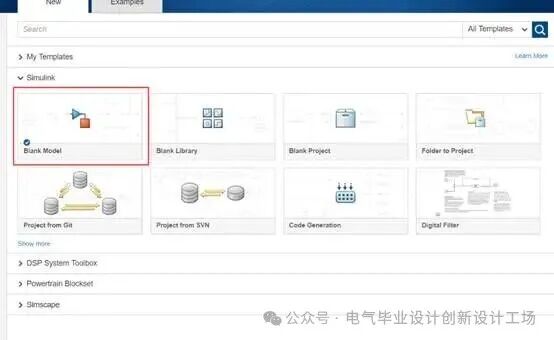
1.Create an empty project
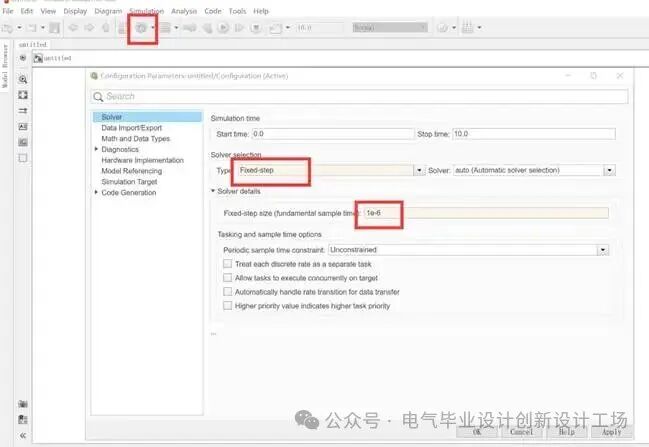
2.Set the solver: discrete fixed step size
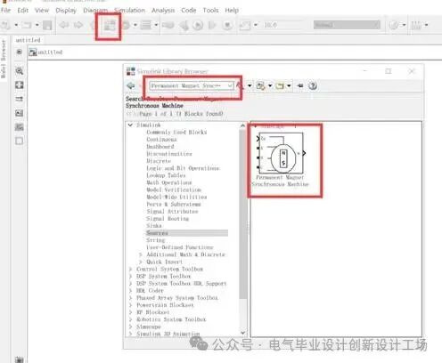
3.Open the simulation library to add components and drag them into the model
a)MotorPermanent Magnet Synchronous Machine
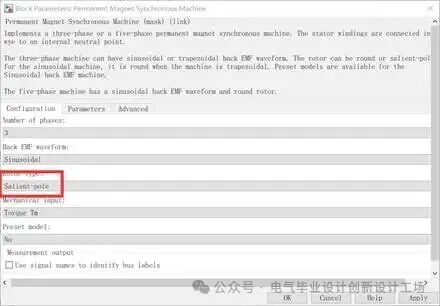
Double-click the motor model, set parameters according toPriusmotor parameters:
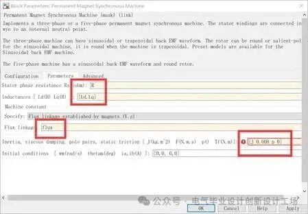
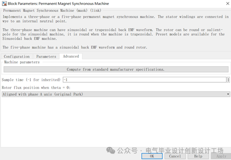
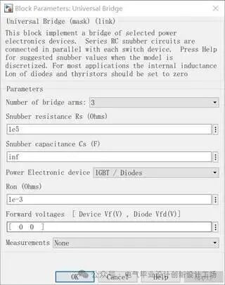
b)Three-Phase Inverter BridgeUniversal Bridge
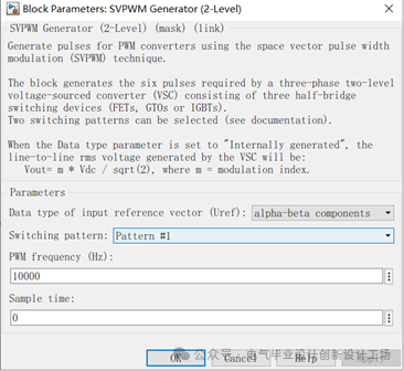
c)SVPWM Generator (2-Level)
d)Similarly, add a DC Voltage Source, coordinate transformation modules (dq0 to Alpha-Beta-Zero, abc to dq0), demux, mux, Bus selector, gain, PID, sum, constant, and Powergui
l Among them, select the coordinate transformation with theAaxis overlap option
l Demux and mux are used for multiplexing and separating signals, used in conjunction with coordinate transformation
l Bus selector is used to extract motor measurements
l Gain is used for formula calculations or unit conversions
l PID is used for the dual-loop controller
l Sum is used for summation and subtraction
l Constant is for constants
l Powergui is required for simulating power electronic devices
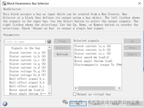
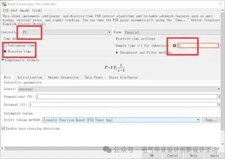
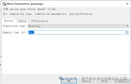
Connect the modules as follows:
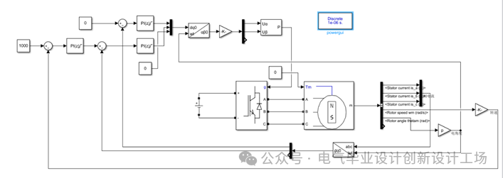
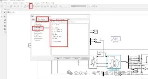
4.Initialize variables
a)Assign values to the previous variables, see the code and input locations below
Tc = 1e-4;
R = 0.07;
Ld = 1.296e-3;
Lq = 2.308e-3;
p = 4;
J=0.005;
flux = 0.207;
Udc=600;
x_p=2*pi*500;
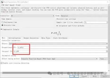
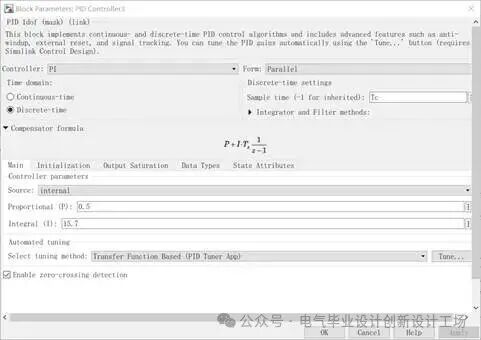
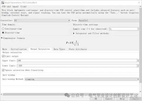
b)PI parameters
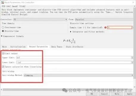
Current loop parameters are set according to the design results from the previous lesson, pay attention to the limits;
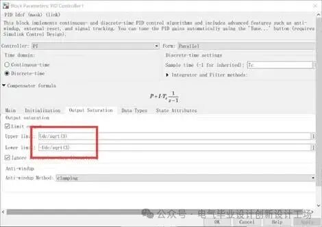
The speed loop is similarly set, with the output limited to plus or minus100A
5.Start simulation
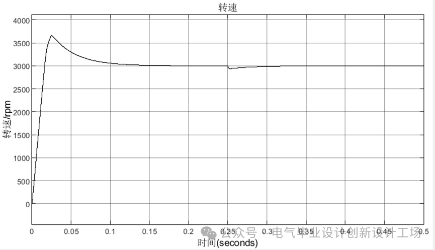
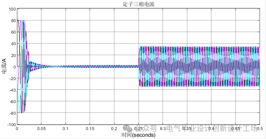
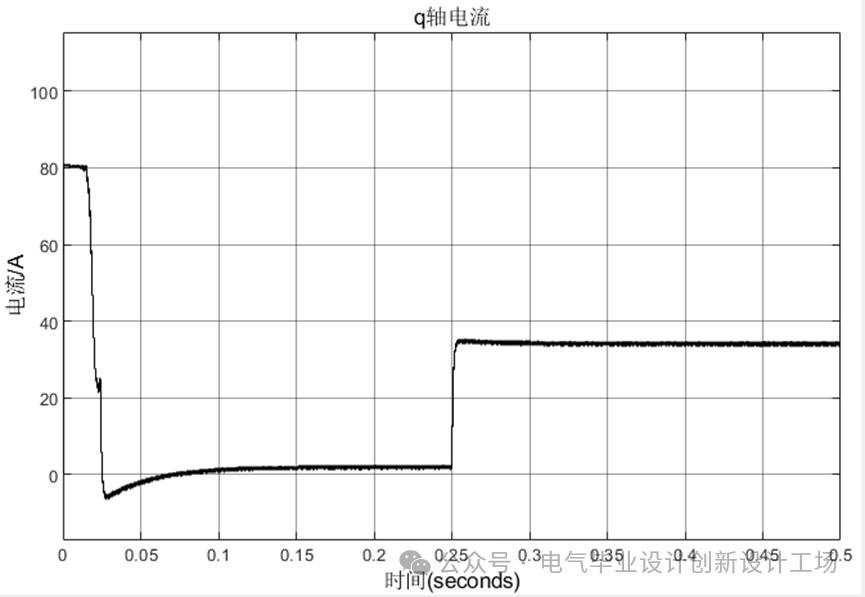
The simulation duration is set to0.5s, with the motor load set to a40Nm step signal for0.25s, and the speed set to3000rpm, usingscope to observe the changes in speed and three-phase current:
Debugging experience:
1.First, adjust the current loop: In fact, this is adjusting the torque control. It is recommended to set the motor’s mechanical port to speed load (in the PMSM motor module parameter settings under configuration-mechanical input-speed), then disconnect the speed loop and directly set it before the current regulator. After adjusting the current loop, change the motor’s mechanical port to torque load, and then reconnect the speed loop for debugging.