Background Knowledge
The DS1307 is an I2C interface real-time clock (RTC) chip, primarily used for independent timing (data retention during power loss), providing accurate year/month/day/hour/minute/second information for devices like Arduino and microcontrollers. It is one of the most commonly used timing modules in hardware DIY projects.
【Core Features】
-
Independent Timing: Built-in 32.768kHz crystal oscillator with a “heartbeat” function, allowing it to keep time without relying on a controller, powered by either main power or a backup battery.
-
Power Loss Memory: Supports CR2032 button battery backup, allowing continuous timing during power outages, with a single battery lasting from several months to years.
-
I2C Communication: Only requires two wires, SDA (data line) and SCL (clock line), to connect to the controller, making wiring simple and not occupying too many pins.
-
Practical Functionality: Supports both 24-hour and 12-hour formats, automatically handles leap years (from 2000 to 2099), with time data stored in internal registers.
-
Low Cost: The chip and module are inexpensive (just a few dollars), offering high cost-performance ratio, suitable for beginner DIY projects.
【Typical Applications】
-
Electronic clocks, timers (like the previous LCD1602 clock);
-
Data collection timestamps (e.g., marking time when sensors record data);
-
Timed triggering scenarios (e.g., scheduled lighting, timed sampling);
-
Time synchronization for smart devices (e.g., IoT nodes, small controllers).
【Key Parameters】
-
Supply Voltage: 2.0V~5.5V (compatible with Arduino 5V/3.3V);
-
I2C Address: Default 0x68 (fixed, cannot be modified);
-
Timing Accuracy: Standard crystal oscillator approximately ±20ppm (daily error ~1.7 seconds), high-precision oscillators can optimize to ±5ppm;
-
Communication Speed: I2C standard mode (100kHz), supports fast mode (400kHz).
In simple terms, the DS1307 is a “mini independent calendar”. Once powered (main power + backup battery), it keeps time continuously. When the controller needs the time, it simply “asks” it through two wires, making it a cost-effective choice for achieving precise timing in hardware projects.
1. Electronic Components Used in the Experiment
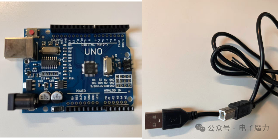
1 Arduino board, 1 USB data download cable
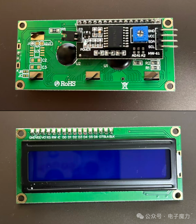
1 LCD1602 IIC LCD display (with integrated driver circuit)
1 DS1307 clock module

2. Experimental Steps
【Wiring Method 1 – Connecting the SDA and SCL Pins of LCD1602 and DS1307 Separately】
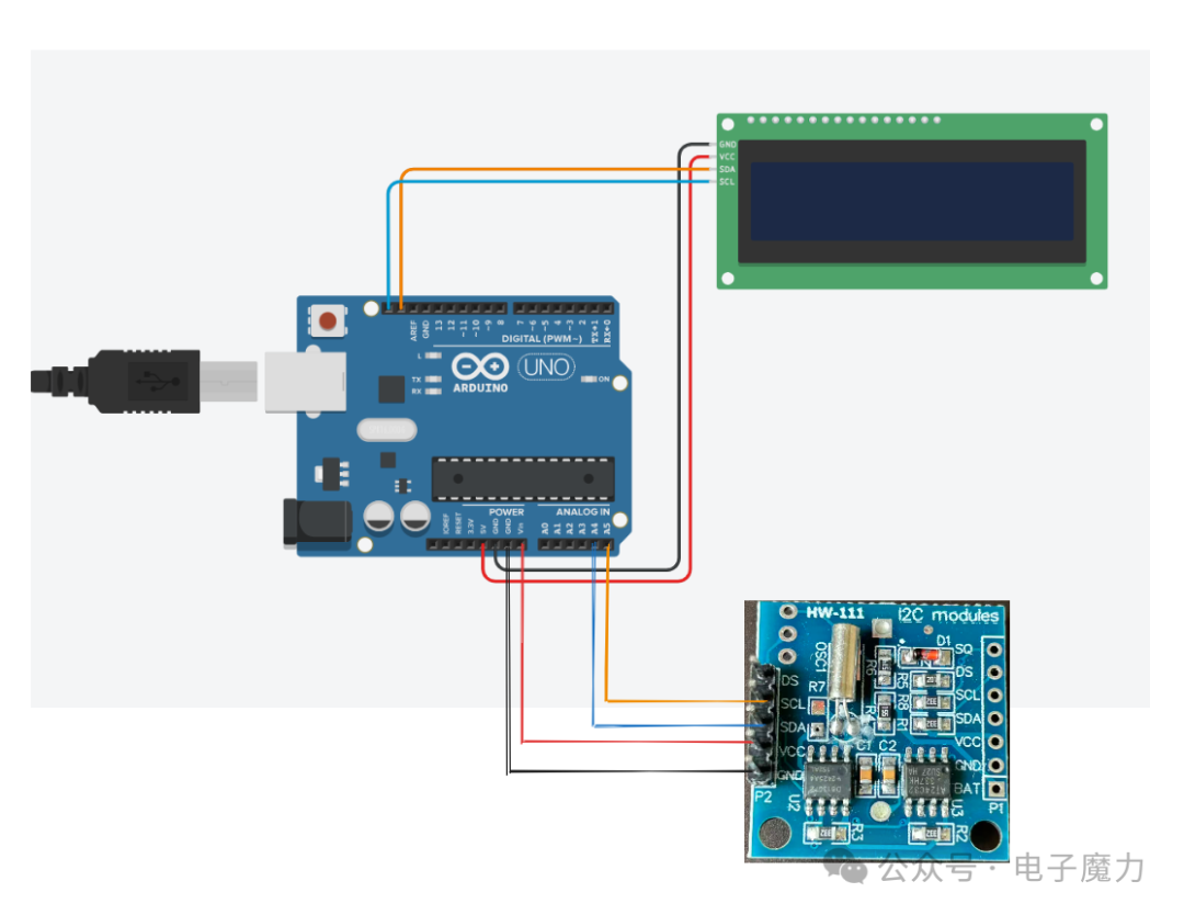
LCD1602 Wiring:
GND → Arduino GND
VCC → Arduino 5V
SDA → Arduino SDA
SCL → Arduino SCL
DS1307 Wiring:
GND → Arduino GND
VCC → Arduino VIN
SDA → Analog Pin 4 (A4)
SCL → Analog Pin 5 (A5)
The SDA (data line) and SCL (clock line) of the DS1307 connect to the A4 and A5 pins of the Arduino. The core reason is that these two pins are the default pins for the hardware I2C bus on the Arduino board. I2C communication requires dedicated hardware module support, and A4/A5 are designed as “native interfaces” for I2C, rather than arbitrary general-purpose pins.
The hardware I2C pins for different Arduino models are fixed (determined by the chip manual and board design). Taking the most commonly used Arduino Uno/Nano as an example:
-
The main control chip is ATmega328P, which integrates an I2C module (called TWI module);
-
The data line (SDA) of this module corresponds to the PC4 pin of the chip, and the clock line (SCL) corresponds to the PC5 pin;
-
During board design, PC4 is routed to the external A4 interface, and PC5 is routed to the A5 interface—thus A4/A5 are essentially “physical extensions of the hardware I2C module”.
In simple terms: the hardware design of the Arduino board binds the I2C module to A4/A5, just like the USB port is specifically for peripherals and the power port is specifically for power supply, making it a “dedicated interface match”.
【Wiring Method 2 – Shared SDA & SCL Interface】
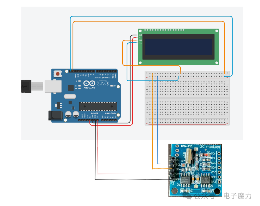
We introduced a breadboard, connecting the SDA pins of the LCD1602 and DS1307 to a common ground, and the SCL pins to a common positive, then connecting the breadboard’s positive and negative to the Arduino’s SCL and SDA, as the internal SCL and SDA of the Arduino can share multiple devices, with different devices accessed via different addresses.
3. Program Code
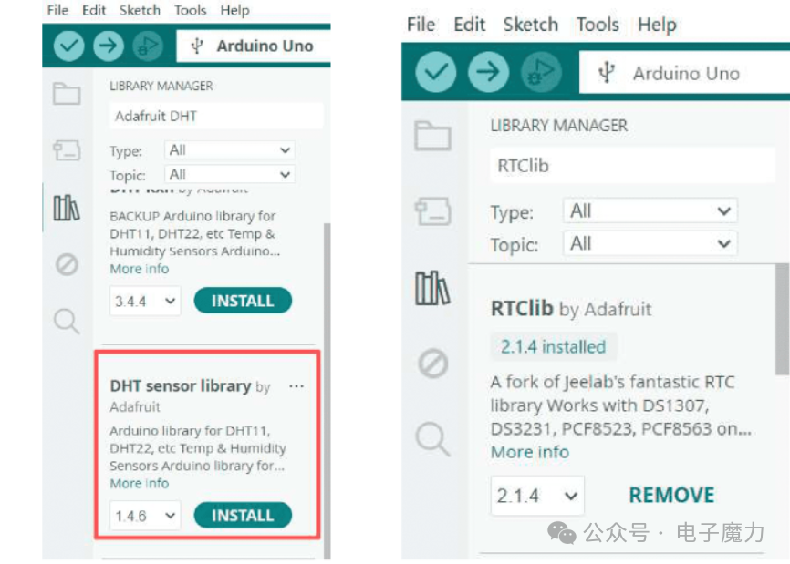
The experimental code requires the inclusion of the LiquidCrystal_I2C.h third-party library to drive the LCD1602 display; the RTClib library is included to operate the DS1307. Search for and install these two libraries in the IDE, noting that dependent libraries also need to be installed together.
// Clock program with time memory feature#include <Wire.h>#include <RTClib.h>#include <LiquidCrystal_I2C.h>LiquidCrystal_I2C lcd(0x27, 16, 2); // LCD address: 0x27 (change to 0x3F if not displaying)RTC_DS1307 RTC;// Weekday mapping table (optional, can be deleted if not needed)const char* weekDays[] = {"Sun", "Mon", "Tue", "Wed", "Thu", "Fri", "Sat"};void setup() { Wire.begin(); lcd.init(); lcd.backlight(); // Turn on LCD backlight (comment out to save power) // 1. Check if the DS1307 module is connected properly if (!RTC.begin()) { lcd.setCursor(0, 0); lcd.print("RTC Connect Err"); lcd.setCursor(0, 1); lcd.print("Check Wiring!"); while (1); // Pause program on connection failure } // 2. Set initial time only during first upload! // Be sure to comment this line after successful upload (otherwise time resets on each power-up) // RTC.adjust(DateTime(2025, 11, 22, 14, 52, 30)); // Year-Month-Day}void loop() { DateTime now = RTC.now(); // Get current time (battery maintains during power loss) // Line 1: Date + Weekday (optional) lcd.setCursor(1, 0); lcd.print(now.year()); lcd.print('-'); lcd.print(now.month() < 10 ? "0" : ""); // Pad with 0 if less than two digits lcd.print(now.month()); lcd.print('-'); lcd.print(now.day() < 10 ? "0" : ""); lcd.print(now.day()); lcd.print(' '); lcd.print(weekDays[now.dayOfTheWeek()]); // Display weekday (0=Sunday) // Line 2: Time (Hour:Minute:Second) lcd.setCursor(3, 1); lcd.print(now.hour() < 10 ? "0" : ""); lcd.print(now.hour()); lcd.print(':'); lcd.print(now.minute() < 10 ? "0" : ""); lcd.print(now.minute()); lcd.print(':'); lcd.print(now.second() < 10 ? "0" : ""); lcd.print(now.second()); delay(1000); // Refresh every second to avoid LCD flicker}4. Experimental Results
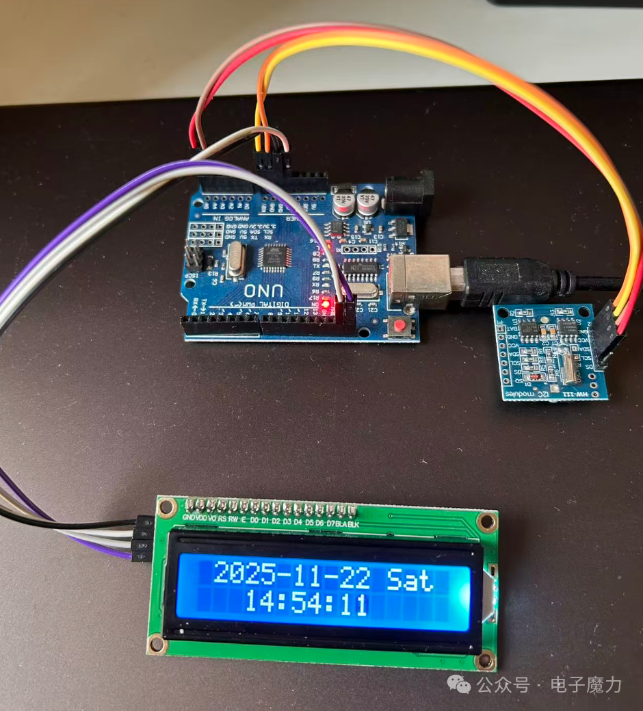
After successfully uploading the program, the LCD1602 screen displays the date, weekday, and real-time, refreshing every second without flickering, showing stable output. After disconnecting the main power supply (USB/adaptor), the DS1307 is powered by the backup battery, maintaining timing without interruption; upon re-powering or pressing the reset button, the LCD directly displays the current accurate time (rather than the initial set time), confirming the memory function is effective, with battery life lasting from months to years.
It is important to note that since we are creating a digital clock that supports power loss memory, the initial upload of the program requires uncommenting this line: RTC.adjust(DateTime(2025, 11, 22, 14, 52, 30)). After the first successful upload, comment out this line and upload again. Since our DS1307 clock module comes with a button battery, it can retain the time internally.
The internal timing function of the DS1307 is provided by a stable 32.768kHz oscillation signal from a quartz crystal, serving as the timing reference:
-
The crystal oscillator utilizes the piezoelectric effect of quartz, generating a fixed frequency vibration (32.768Hz, meaning it vibrates 32,768 times per second);
-
The signal is internally divided by the chip 15 times, reducing it to a 1Hz pulse (once per second);
-
The 1Hz pulse drives the internal register counting and carry (seconds → minutes → hours → days), achieving real-time timing;
-
The stability of the crystal oscillator determines the timing accuracy, and the backup battery continues to power it during power loss, ensuring uninterrupted timing (the core of power loss memory).
Wiring physical diagram:
Experimental Video:
The code mentioned in this article has been uploaded to Gitee, see the link: https://gitee.com/webxiaohua/arduino-learn/tree/master/27_shi_zhong_xian_shi